
Large wind wheel single-stage wheel gear power generation

A power generation device and gear technology, which is applied in electromechanical devices, wind power generation, wind engines, etc., can solve problems such as heavy transmission system chains, and achieve the effect of simplifying energy consumption

Inactive Publication Date: 2010-09-01
黄金伦
View PDF0 Cites 0 Cited by
  • Summary
  • Abstract
  • Description
  • Claims
  • Application Information

AI Technical Summary

Problems solved by technology

[0002] In order to improve efficiency, efforts are made to increase the length of the blades to obtain high blade tip speeds, but the existing technologies seem to transmit wind energy to the hub in the form of long moment arms of long blades, so that the stress of the hub is concentrated and made thick, and the petiole is also Especially heavy... and the transmission system chain is long: for example, with hubs, dials, main shafts, gear speed increasers

Method used


Image

  • Large wind wheel single-stage wheel gear power generation
  • Large wind wheel single-stage wheel gear power generation
  • Large wind wheel single-stage wheel gear power generation

Examples


Embodiment Construction

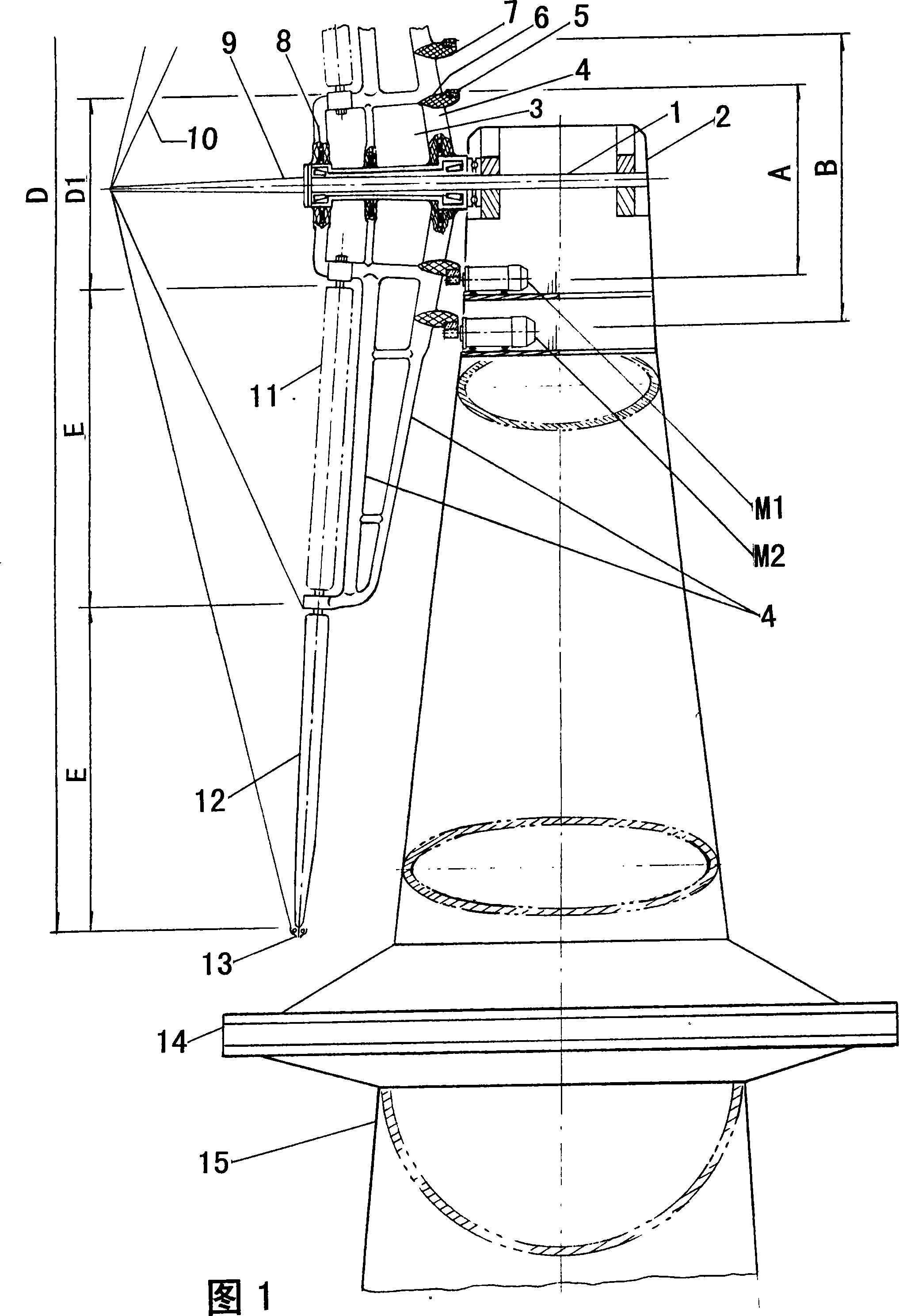
[0009] see figure 1 , the main shaft 1 is fastened in the tower head 2, the main shaft does not rotate, it only plays the role of supporting the center of the wind wheel, and no longer serves as a transmission. Wheel hub 3 can rotate freely through bearings. Three pairs of wheel stays 4 with a distance of 120° are arranged on the outer cylindrical surface of the wheel hub 3 (for the convenience of the view, the upper and lower wheel stays 4 of the wheel hub 3 are developed into a symmetrical layout view), and the inner and outer ring gears 5 are respectively installed on the On the inner ring 6 and the outer ring 7, and make the pitch circle diameter A=30m of the ring gear on the inner ring, and the pitch circle diameter B=45m of the ring gear on the outer ring. Now use the ring gear pitch circle A (①30m) to drive the generator M1, and the ring gear pitch circle B (Φ45m) to drive the generator M2 (both cooperating with the small teeth on each generator shaft respectively).

...


PUM


Abstract

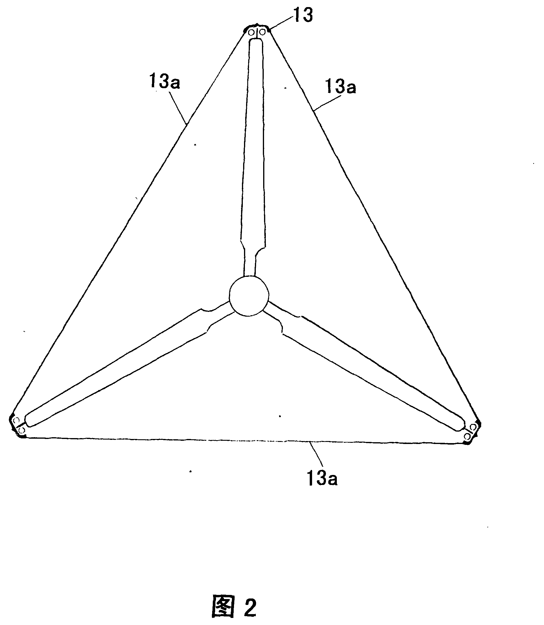
A big wind wheel single-grade gear generator is disclosed, which is characterized in that a main shaft 1 is tightened on a tower head 2 for centering action of a wind wheel only, the wind wheel adopts a hub 3 and a wheel support 4 to connect as an integral for supporting an inner vane 11 and an outer vane 12 to approach external diameter of big circumference as near as possible in order to improve the speed and efficiency of the vane tip. Simultaneously, the segment is an axial inner vane 11 and outer vane 12, which not only reaches the goal of hyper-big wind wheel, but also shortens the vanelength and reduces bending torque and vane weight. The wheel support 4 can be an inner ring which is provided with a gear coil 5 and big gear kinetic energy output device of the external ring 7, which separately gear small gear of a motor M1 and a motor M2 to generate. The big wind wheel single-grade gear generator has the advantages of that firstly saving a verbose drive chain and energy consumption of the prior technique, secondly being beneficial to break through bottleneck of the hyper big wind wheel.

Description

technical field [0001] The invention belongs to the field of three-blade wind wheel power generation, and relates to a super-large wind wheel structure and a driving generator mode. Background technique [0002] In order to improve efficiency, efforts are made to increase the length of the blades to obtain high blade tip speeds, but the existing technologies seem to transmit wind energy to the hub in the form of long moment arms of long blades, so that the stress of the hub is concentrated and made thick, and the petiole is also Especially heavy... and the transmission system chain is long: for example, with hubs, dials, main shafts, and gear speed increasers. Contents of the invention [0003] The purpose of the invention is to simplify the transmission system, change the structure of the hub, save the large and heavy nacelle, and break through the bottleneck of large-scale wind wheel due to the concentration of stress at the root of the blade and hinder the large-scale. ...

Claims


Application Information

Patent Timeline
Patent Type & Authority Patents(China)
IPC IPC(8): F03D9/00F03D1/06H02K7/18F03D9/25
CPCY02E10/725Y02E10/721Y02E10/72
Inventor 黄金伦
Owner 黄金伦
Learn More