

Multi- flow path transverse circulation gypsum board drying apparatus and its drying method
A drying equipment and multi-process technology, applied in drying, dryers, lighting and heating equipment, etc., can solve the problems of high energy consumption, high production cost, complex structure, etc., achieve uniform drying effect, reduce power consumption, etc. Consumption, the effect of improving thermal efficiency
- Summary
- Abstract
- Description
- Claims
- Application Information
AI Technical Summary
Problems solved by technology
Method used
Image

Examples
Embodiment 1
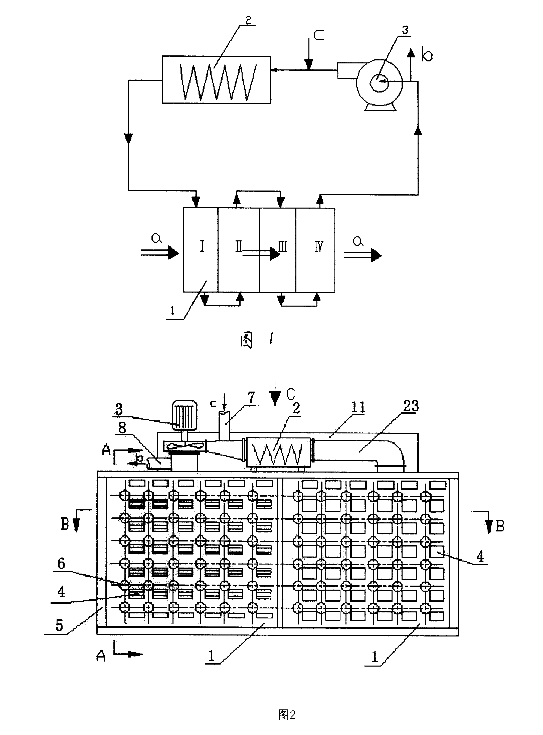
[0046] Figure 1 is a schematic flow diagram of hot air as a drying medium and dried materials in drying section 1, which shows four drying sections, that is, four drying processes. The dryer 5 is divided into several drying areas in the direction a of material movement, and each drying area is divided into four drying sections 1 along the main channel 9 separated from each other by the air duct and wind-blocking plate 16, and each drying section 1 The main channels are separated by airflow baffles 15; the air outlet end of each drying section 1 is connected with the air inlet end of the next drying section. In its drying zone, the hot air that provides heat for the drying process adopts a four-flow cross-flow circulation, that is, the hot air passes through four drying zones in sequence in each drying zone in accordance with the flow direction perpendicular to the conveying direction of the material to be dried. Each time a drying section passes through, the temperature of the...
Embodiment 2
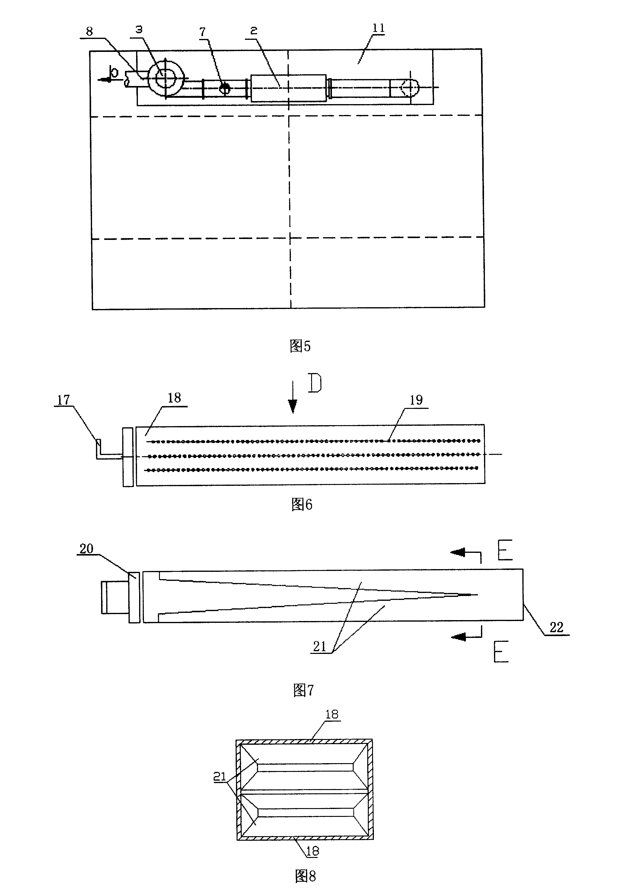
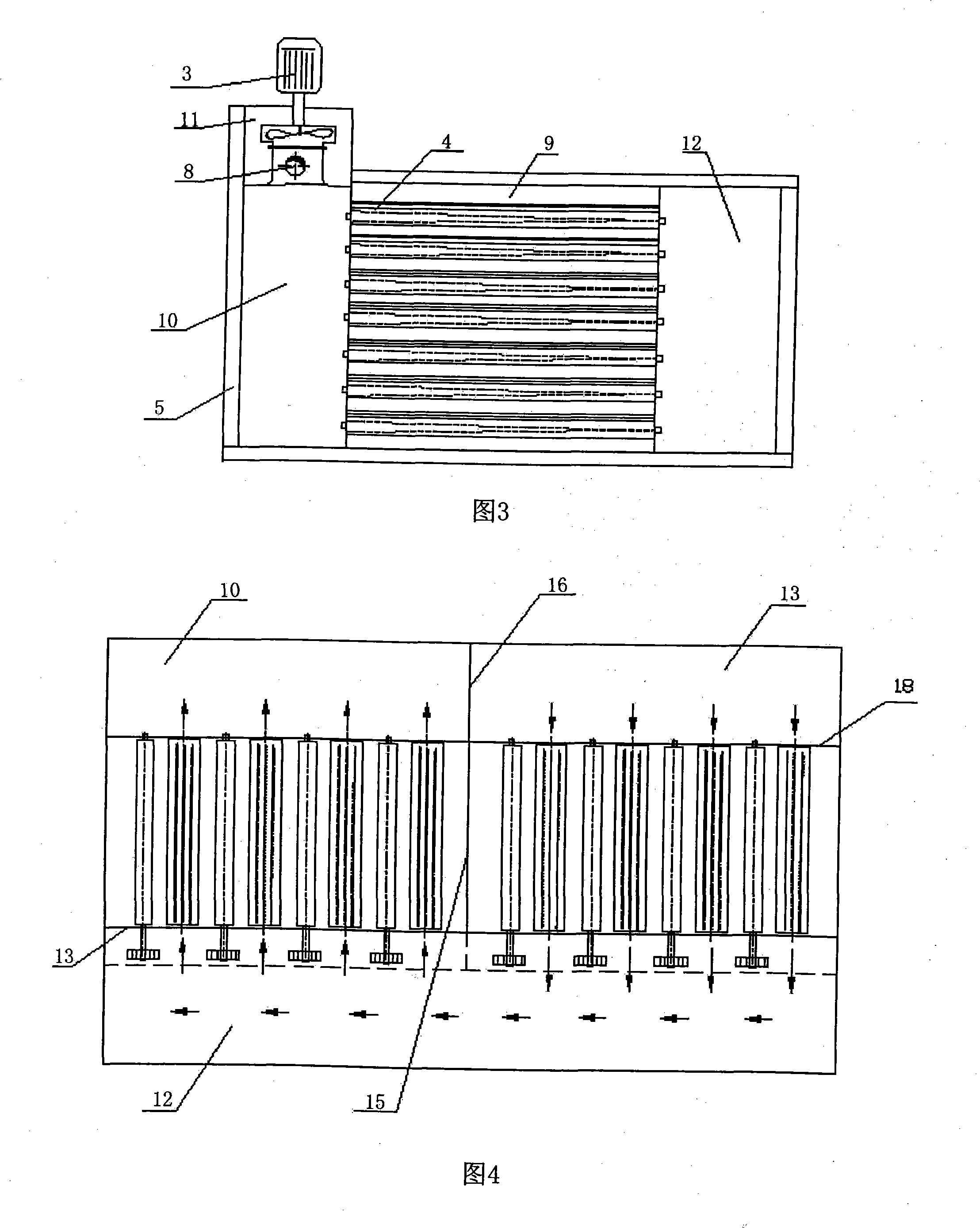
[0048] Figures 2 to 5 are structural schematic diagrams of the double-flow drying section, which uses a two-stage drying section, which is a double-flow process. A drying zone of the dryer 5 shown is composed of two closed and closely connected drying sections 1; each drying section 1 is provided with multi-layer conveying rollers 6, which are perpendicular to the conveying direction of the gypsum board. An air blowing pipe 4 is arranged between every two adjacent conveying rollers 6, and the support bearings at both ends of the conveying rollers 6 are fixed on the beam of the corresponding dryer 5, and the conveying rollers 6 are arranged in the main passage 9, The two sides of the main passage 9 are respectively provided with a non-transmission side auxiliary passage 10 and a transmission side auxiliary passage 12, wherein the upper part of the non-transmission side auxiliary passage 10 is provided with a top passage 11, and a circulating fan 3 and a heating device are instal...
PUM
 Abstract
Description
Claims
Application Information