Star sensor polarity inspection method

A star sensor and inspection method technology, applied in the field of optical sensors, can solve problems such as the technology and method of polarity testing of star sensors that have not been seen, and achieve the effects of intuitive and clear judgment basis, simple method, and less testing equipment

Active Publication Date: 2008-08-06
BEIJING INST OF CONTROL ENG
View PDF0 Cites 17 Cited by
  • Summary
  • Abstract
  • Description
  • Claims
  • Application Information

AI Technical Summary

Problems solved by technology

[0004] At present, there are no materials and reports related to the te

Method used


Image

  • Star sensor polarity inspection method
  • Star sensor polarity inspection method
  • Star sensor polarity inspection method

Examples


Embodiment Construction

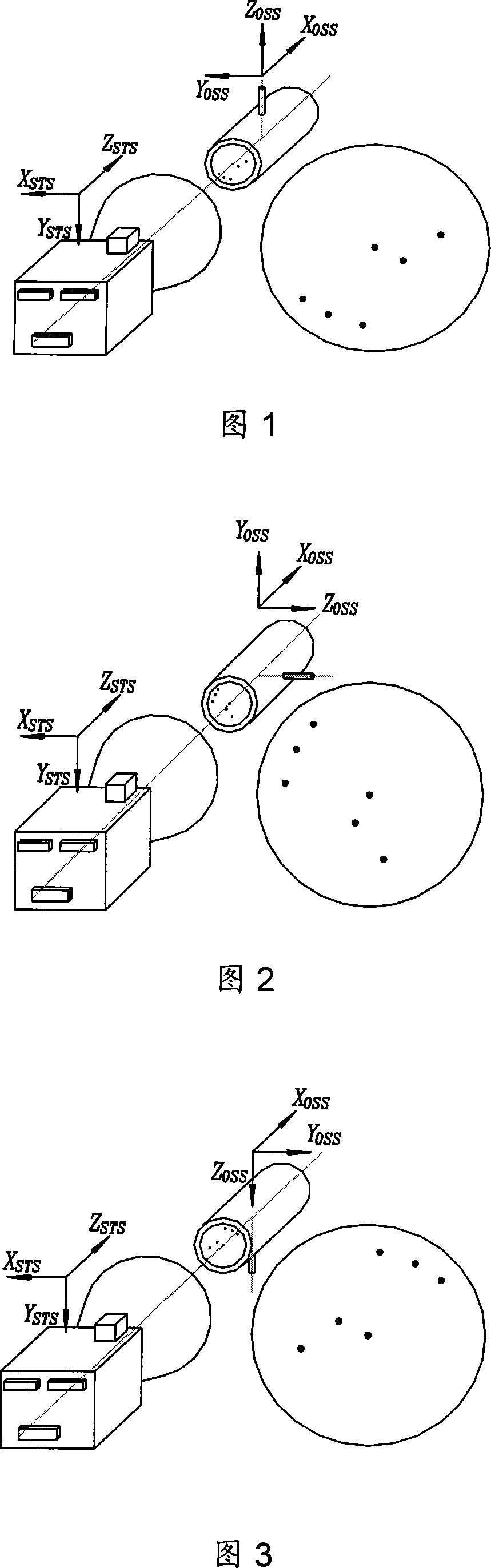
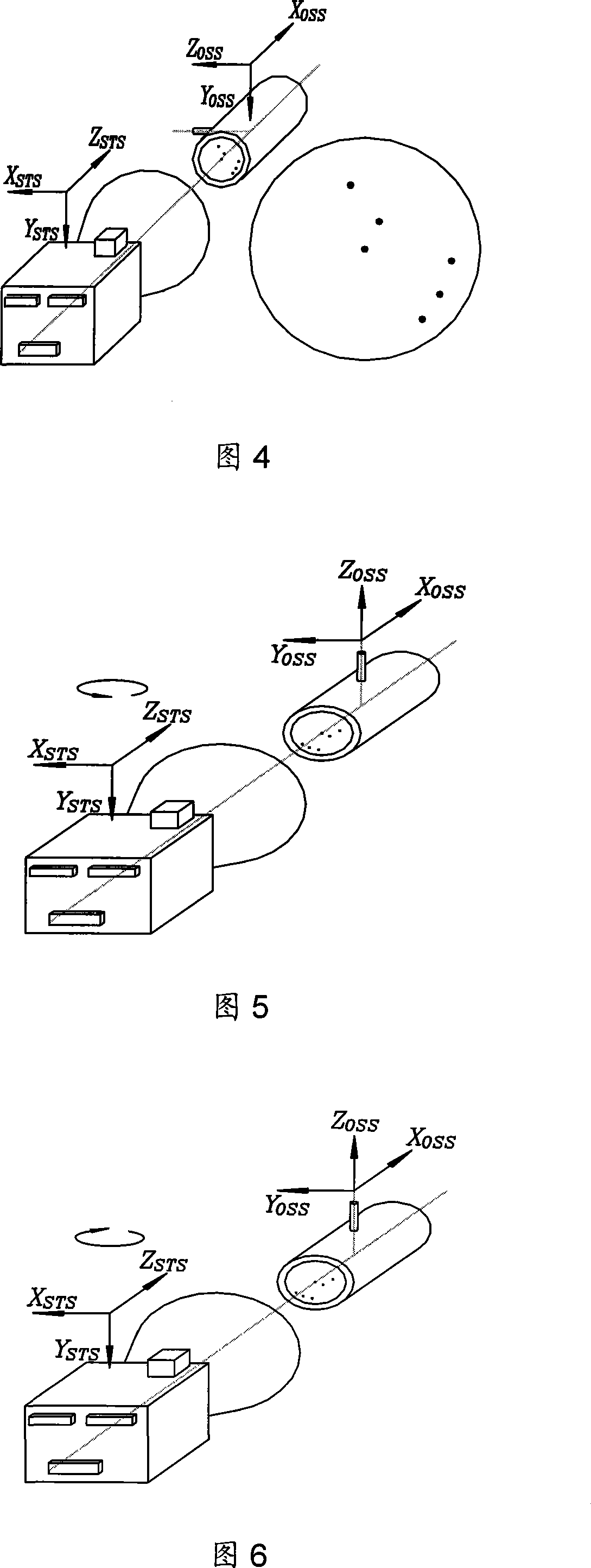
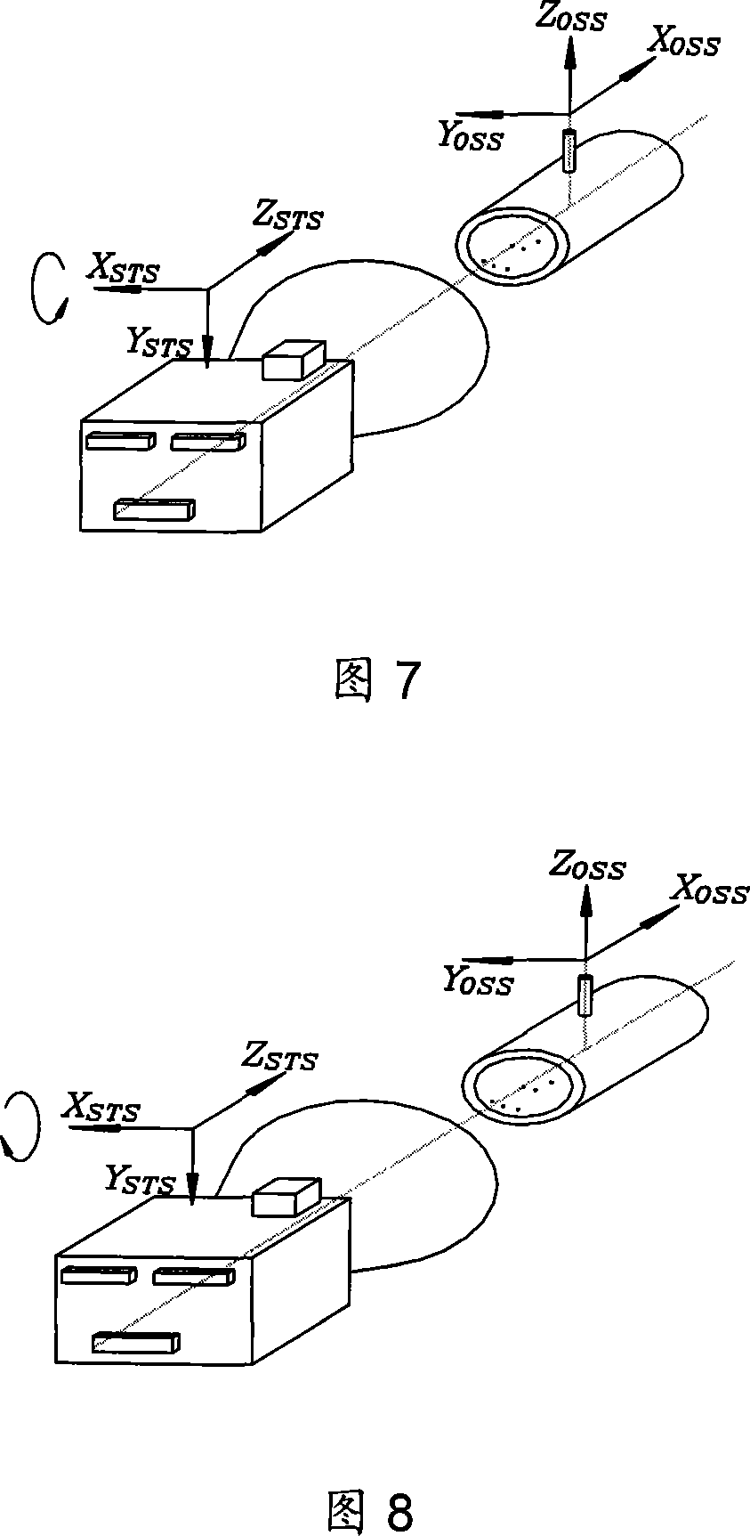
[0020] For the star sensor involved in the embodiment of the present invention, please refer to the article "Integrated Small Star Sensor" in the 2002 issue of "Aerospace Control", and for the static star simulator involved, please refer to China Aerospace Publishing House 2003 Published "Missile and Aerospace Series-Satellite Control System Simulation Technology" edited by Liu Liangdong.

[0021] First define the star sensor measuring coordinate system and the positive and negative directions of the star sensor's rotation angle. The definition method of the star sensor measuring coordinate system is: taking the centroid of the star sensor as the origin of the star sensor measuring coordinate system; taking the vector passing through the origin, perpendicular to the bottom surface of the installation and pointing to the outer space of the star sensor as the measuring coordinate system + Y axis; the vector passing through the origin, parallel to the optical axis of the star sensor ...


PUM


Abstract

Disclosed is a polarity testing method for a star sensor, which is composed of firstly defining positive and negative directions of a measuring coordinate system and a corner of the star sensor, defining a static star sensor coordinate system and an experimental inertial coordinate system, then docking a static star sensor and the star sensor to enable an optical axis to parallel to an optical axis of the star sensor, observing a stimulated star map generated by the static star sensor and outputting attitude data by the star sensor, judging correctness of the output polarity of the star sensor by comparing output attitude of the star sensor and inertial attitude corresponding to the stimulated star map, then rotating the star sensor to enable the star senor and the static sensor to form a proper angle, then observing the stimulated star map generated by the static star stimulator and outputting attitude data by the star sensor, and judging the correctness of the output polarity of the star sensor by comparing actual variation trend and theoretical variation trend of the output attitude after and before the rotation of the star sensor.

Description

Technical field [0001] The invention belongs to the field of optical sensors, and relates to a method for checking the polarity of a star sensor. Background technique [0002] The star sensor is an optical attitude sensor that takes stars as the object of observation. It is mainly used for the attitude measurement tasks of spacecraft such as satellites and spacecraft in orbit. The star sensor in the usual sense is a star sensor in the star map mode, that is, it first needs to take an image of the starry sky in a certain area, and then detect the star image in the image through the image processing algorithm, and use the star recognition technology to confirm the star. Observe the "identity" of the star and finally complete the task of attitude measurement. The attitude obtained by the star sensor measurement is essentially the direction of each axis of the star sensor's measurement coordinate system in the geocentric inertial coordinate system. [0003] The so-called star sensor ...

Claims


Application Information

Patent Timeline
IPC IPC(8): G01C21/24G01C25/00B64G1/36
Inventor 黄欣陈义庆卢欣武延鹏孙昕赵玮
Owner BEIJING INST OF CONTROL ENG
Why Eureka
Try Eureka