

Multi-resistance band and ultra-broadband antenna realized based on mount aperture erosion
An ultra-wideband antenna and slot technology, which is applied in the field of ultra-wideband antenna design, can solve problems such as singleness, the influence of antenna working bandwidth, and the inability to suppress multiple stopbands, and achieve the effects of good repeatability, simple structure, and low cost
Inactive Publication Date: 2008-08-06
SOUTHEAST UNIV
View PDF0 Cites 18 Cited by
- Summary
- Abstract
- Description
- Claims
- Application Information
AI Technical Summary
Problems solved by technology
At present, many stopband antennas only have a single stopband and cannot suppress multiple stopbands; or, the working bandwidth of antennas with two stopbands is affected and reduced
Method used
View moreImage
Smart ImageViewing Examples

Examples
Embodiment 1
[0023] Embodiment 1 Patch slit etching ultra-wideband multi-stopband antenna.
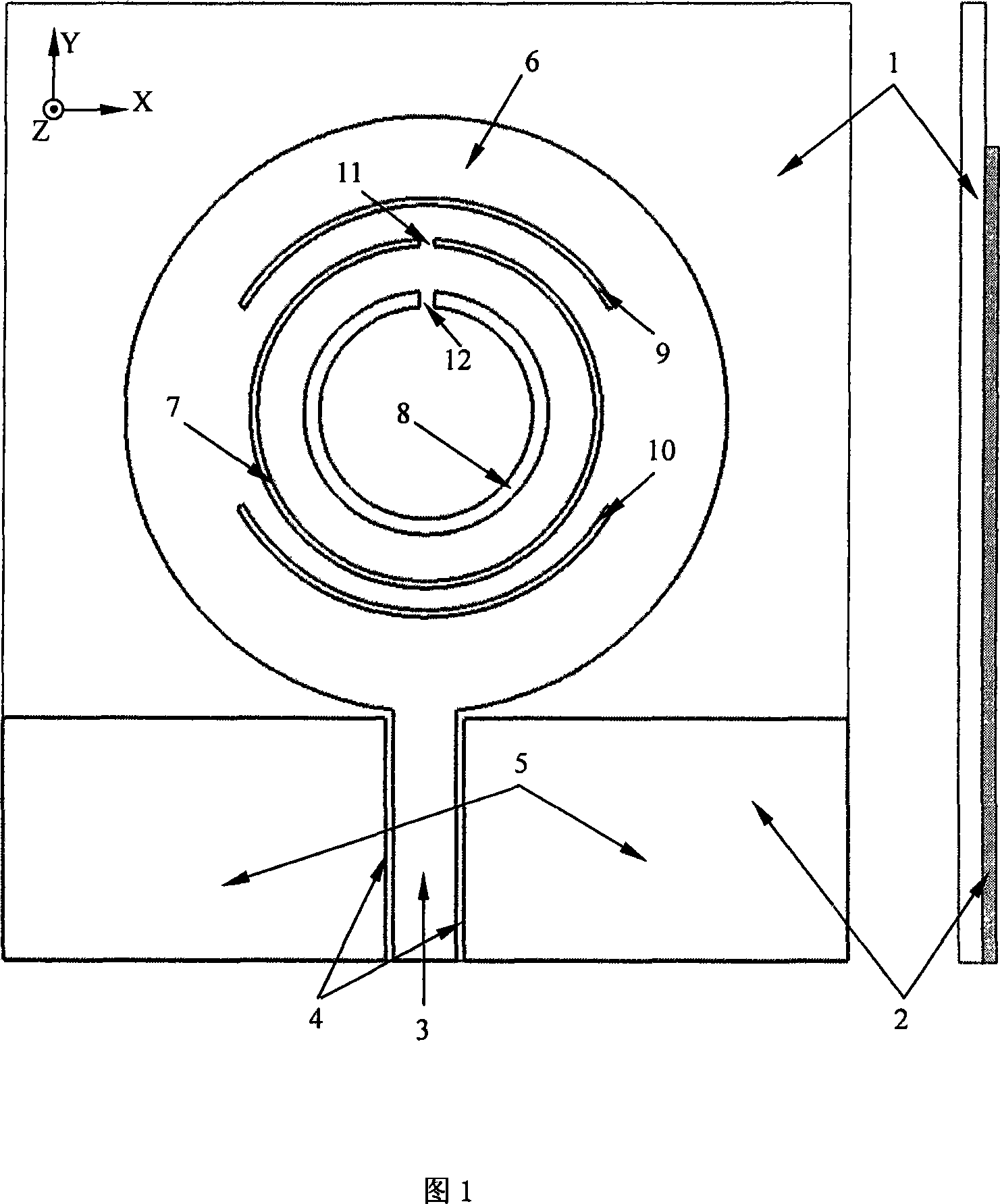
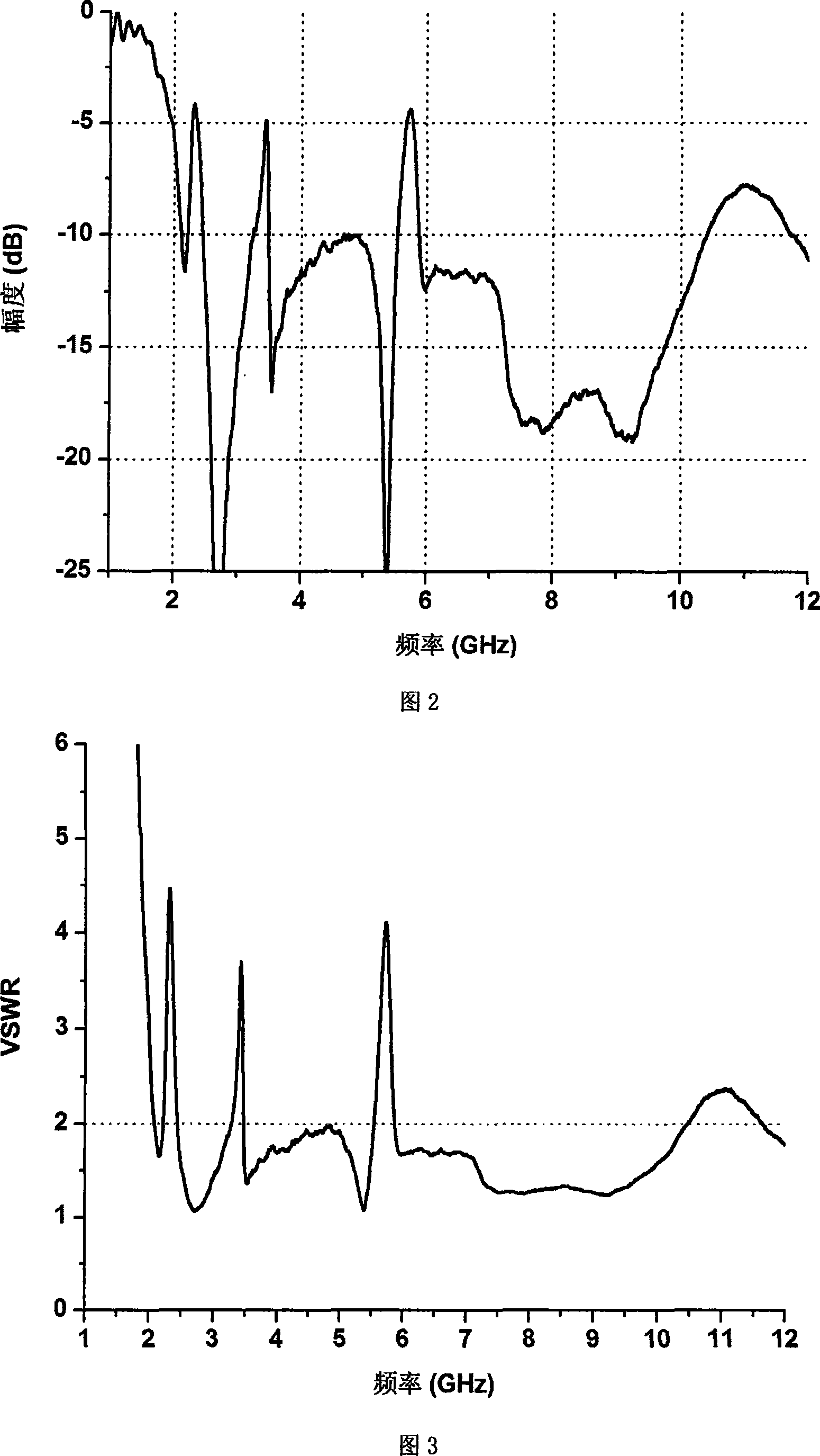
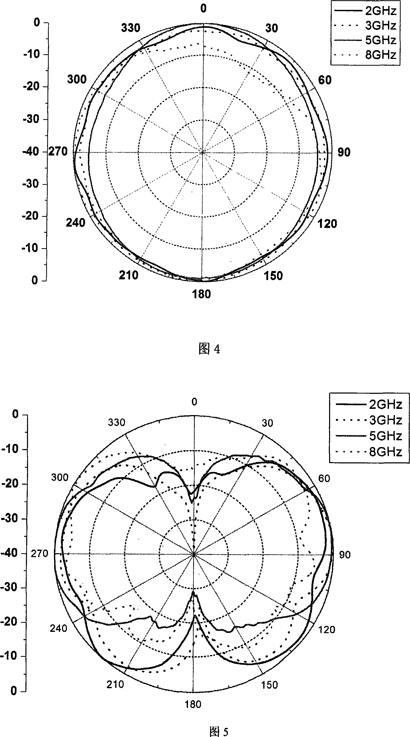
[0024] The structure of the antenna is shown in Figure 1, and the unit of size is mm. The size of the substrate in this embodiment is 47×54×1. The measured antenna reflection coefficient, input voltage standing wave ratio (VSWR) and the results of the directivity diagrams of the lower XOZ, YOZ, and XOY planes are shown in Figures 2 to 6.
Login to View More PUM
 Abstract
The present invention relates to a multi-stopband ultra-wideband antenna realized through patch gap etching, which consists of a dielectric substrate (1) and a metal clad layer(2) on the dielectric substrate (1). A feeder line part adopts a coplanar waveguide form, and consists of a signal line (3), gaps (4) and metal areas (5) which are symmetrically distributed on two sides of the signal line (3); a radiation unit (6) adopts a disk form; an extended end of the signal line (3), which is slightly longer than the metal areas (5) on two sides, is connected with the radiation unit (6); the antenna has ultra-wideband characteristic, which can meet the requirements of ultra-wideband communication systems; meanwhile, the antenna can generate stopbands at three frequencies, thereby having the performance of resisting multiple frequency point interference. As the frequency of the antenna stopband can be freely regulated by changing etching gap length, the antenna has stopband adjustability, which can satisfy the application in some special interference frequency occasions. In addition, the increase of etching gaps can realize more stopband characteristics.
Description
technical field [0001] The invention is an ultra-wideband (Ultra-Wideband, UWB) antenna design technology suitable for anti-multi-frequency signal interference. It belongs to the technical field of antenna design. Background technique [0002] Ultra-wideband communication system has many advantages such as low complexity, low cost, anti-multipath and anti-aliasing, etc. It is suitable for the development of high-speed communication and has been widely used. In recent years, as an important part of UWB systems, UWB antennas have also received more attention, and the corresponding design requirements have also become higher and higher. At present, in the microwave frequency band, there are a large number of services in the lower frequency band and it is very crowded. Since the ultra-wideband communication system occupies a very wide frequency band (for example, the UWB frequency band recognized by the US FCC is 3.1GHz-10.6GHz), there are inevitably Problems with interfering ...
Claims
Login to View More Application Information
Patent Timeline
 IPC IPC(8): H01Q1/38H01Q13/10
Inventor洪伟张彦蒯振起周健义
OwnerSOUTHEAST UNIV