
Acentric timing and speed-stabilized motor

A technology of stable speed and motor shaft, which is applied in the direction of motor control, electrical components, control systems, etc., can solve the problems of inability to use motor speed regulation and small control current, and achieve the effect of easy production and low cost

Inactive Publication Date: 2008-08-06
李待言
View PDF0 Cites 3 Cited by
  • Summary
  • Abstract
  • Description
  • Claims
  • Application Information

AI Technical Summary

Problems solved by technology

Since the current centrifugal switch is a built-in type, the motor needs to be turned on to adjust the motor speed, so it can only be used for motor speed stabilization and not for motor speed regulation.
Another defect of the centrifugal switch is that due to the limitation of the spark elimination circuit, its control current is small, so it can only be used for small motors.

Method used


Image

  • Acentric timing and speed-stabilized motor
  • Acentric timing and speed-stabilized motor
  • Acentric timing and speed-stabilized motor

Examples


Embodiment Construction

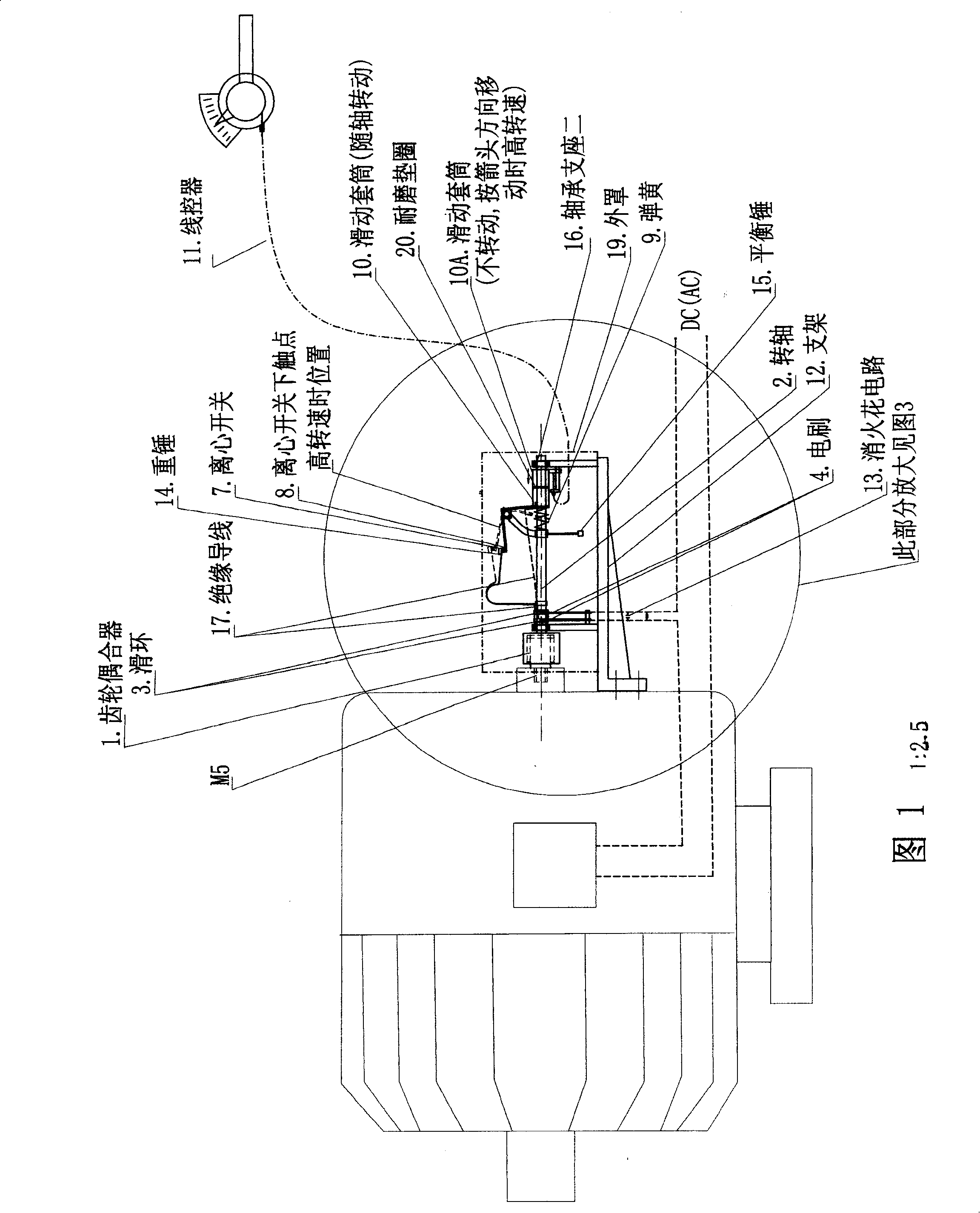
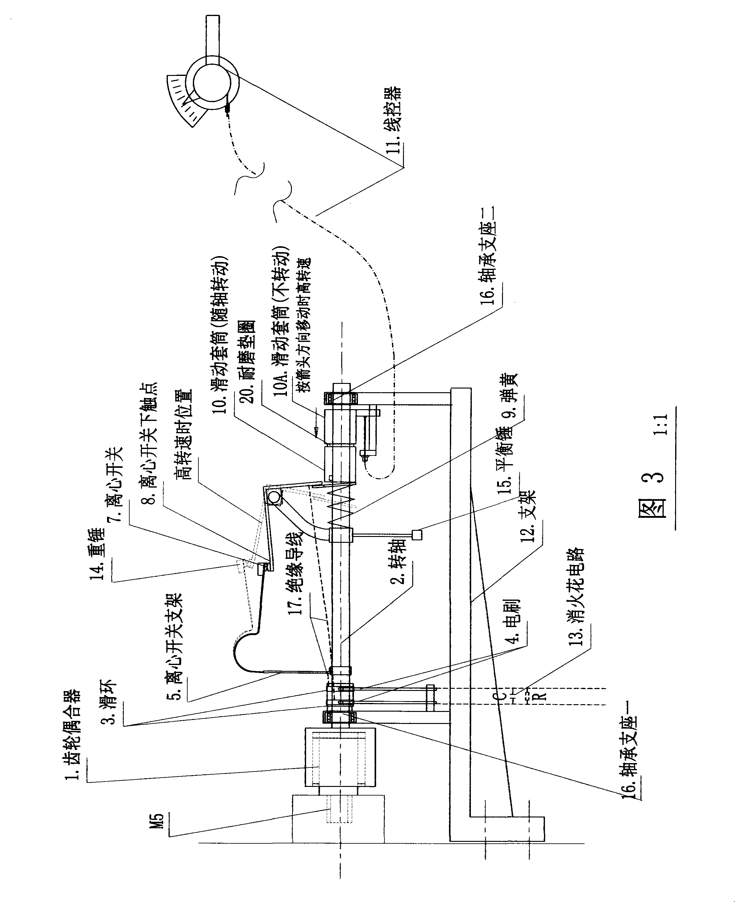
[0019] In Figure 1, the centrifugal speed governor (circle part) is mounted on the end shaft of the motor. The power enters the motor after being controlled by a centrifugal switch. (for small motors) See Figure 3 and Figure 2 for the description of each component in the figure.

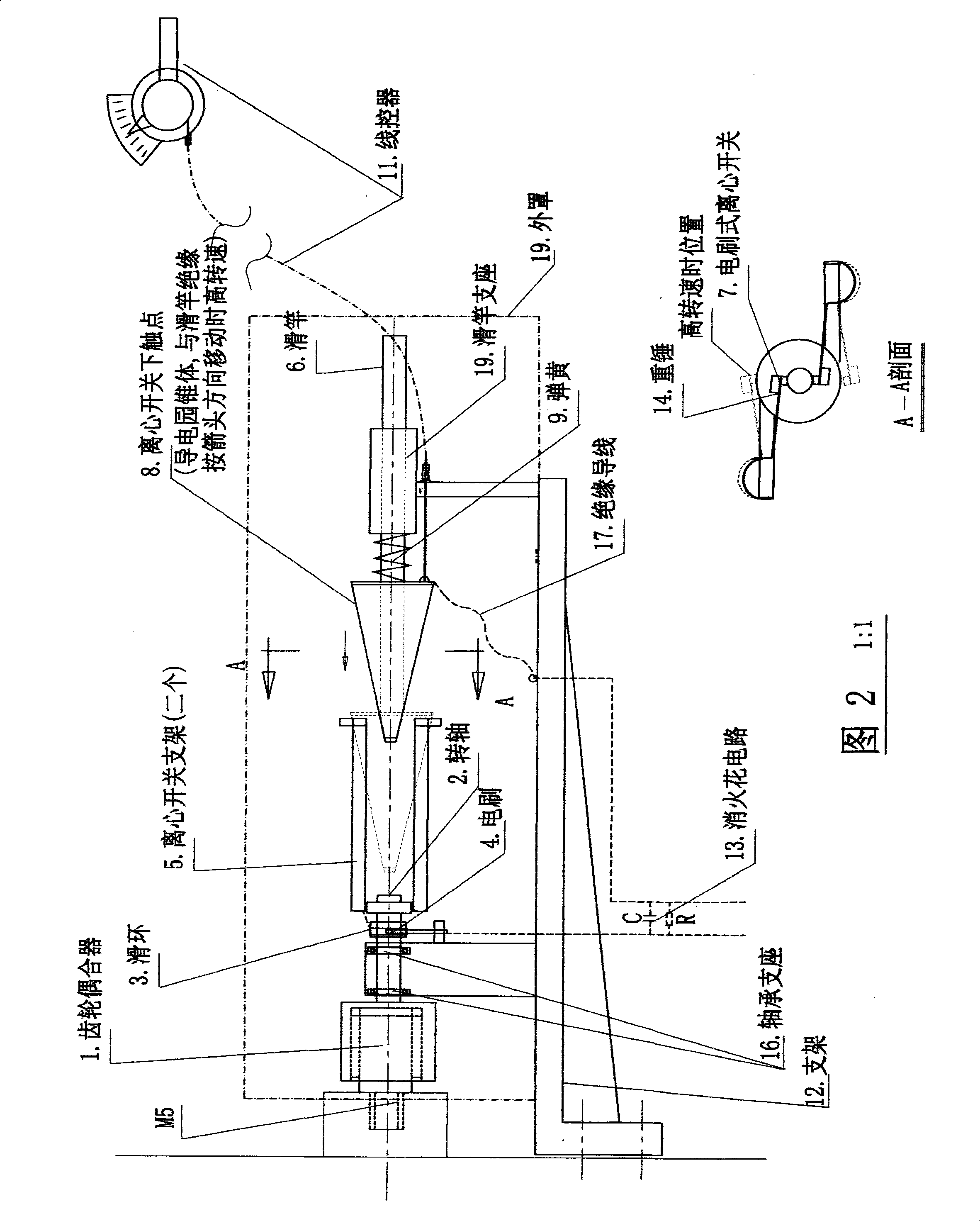
[0020] Fig. 2 is an enlarged view of the first embodiment of the centrifugal governor. In the figure, the inner gear of the gear coupler 1 is fixed on the motor shaft with M5 screws, the outer gear of the gear coupler 1 and the centrifugal switch shaft 2 are fixed on the bracket 12 with the bearing support 16, and the bracket 16 is fixed on the motor casing. The power supply is connected to the brush type centrifugal switch 7 through the brush 4, the slip ring 3 and the centrifugal switch bracket 5, and the brush type centrifugal switch 7 is driven to rotate through the gear coupler 1 when the motor rotates. The lower contact 8 of the centrifugal switch is a non-rotating conductive cone, which is m...


PUM


Abstract

The invention provides a speed regulating and stabilizing motor capable of controlling the rotate speed of the motor accurately and is mainly used for the stepless speed regulation and stabilization of ordinary DC motors and AC motors. The invention mainly comprises a centrifugal speed regulator which is fixed on a projecting shaft at the tail of the motor. When a motor shaft rotates, a centrifugal switch on the centrifugal speed regulator is driven to rotate at the same time by the gear coupling. When the rotate speed of the motor surpasses the presetting value, the centrifugal switch is off; otherwise, the centrifugal switch is on. The input current of the motor flows through an electric brush and the centrifugal switch is used to control the on and off time, thereby controlling the rotate speed of the motor. The rotate speed is regulated by the drive-by-wire or a servo-actuator to regulate the pressure of the centrifugal switch; if the pressure is great, the rotate speed is regulated to be high; if the pressure is small, the rotate speed is regulated to be slow. The application of a thyristor amplifying circuit to a large-sized motor ensures that the motor with high voltage and great current can be controlled even if the current flowing through the centrifugal switch and the voltage are small.

Description

Technical field [0001] The invention is used for stepless speed regulation and speed stabilization of common AC and DC motors. Background technique [0002] At present, the mechanical speed-stabilizing circuit in which a centrifugal switch is connected in series on the circuit inside the motor to stabilize the motor speed has been applied for a long time. The circuit is based on the principle that the centrifugal force is proportional to the rotational speed. When the rotational speed is higher than the set value, the centrifugal switch disconnects the motor circuit under the action of the centrifugal force to reduce the motor speed to the set value; when the rotational speed is lower than the set value, The centrifugal switch closes the circuit, causing the motor speed to increase. Since the centrifugal switch is a built-in type at present, the motor needs to be turned on to adjust the motor speed, so it can only be used for motor speed stabilization and not for motor spee...

Claims


Application Information

Patent Timeline
Patent Type & Authority Applications(China)
IPC IPC(8): H02P29/00
Inventor 李待言
Owner 李待言
Learn More