Making method for miniature sound part

A manufacturing method and technology of sound-generating devices, applied to sensors, electrical components, etc., can solve problems such as polluting the diaphragm, unstable product performance, and glue flowing to other parts, and achieve the effect of improving performance

Active Publication Date: 2011-07-13
AAC ACOUSTIC TECH (CHANGZHOU)CO LTD
View PDF0 Cites 0 Cited by
  • Summary
  • Abstract
  • Description
  • Claims
  • Application Information

AI Technical Summary

Problems solved by technology

In this conventional operation method, when using a machine to brush or spray glue on the parts that need to be joined on the diaphragm or the upper cover, the glue may flow to other parts, resulting in contamination of the diaphragm and unstable product performance.

Method used


Image

  • Making method for miniature sound part
  • Making method for miniature sound part
  • Making method for miniature sound part

Examples


Embodiment Construction

[0019] The present invention will be further described below in conjunction with the accompanying drawings and embodiments.

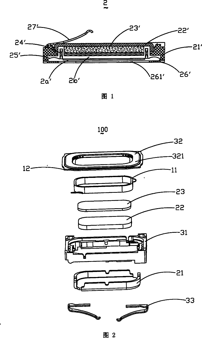
[0020] Such as figure 2 As shown, the micro-sounding device 100 of the present invention includes a vibration system, a magnetic circuit system and an auxiliary system, wherein the vibration system includes a diaphragm 12 and a voice coil 11, and the magnetic circuit system includes a magnetic bowl 21 and a permanent magnet accommodated in the magnetic bowl 21 22 and pole piece 23, the magnetic bowl 21 and the permanent magnet 22 and the pole piece 23 form a magnetic gap (not shown) to accommodate the voice coil 11, and the auxiliary system includes a basin frame 31 for accommodating the magnetic bowl 21, a cover connected with the basin frame 21 The upper cover 32 and the conductive strips 33 installed at opposite corners of the basin frame 31 .

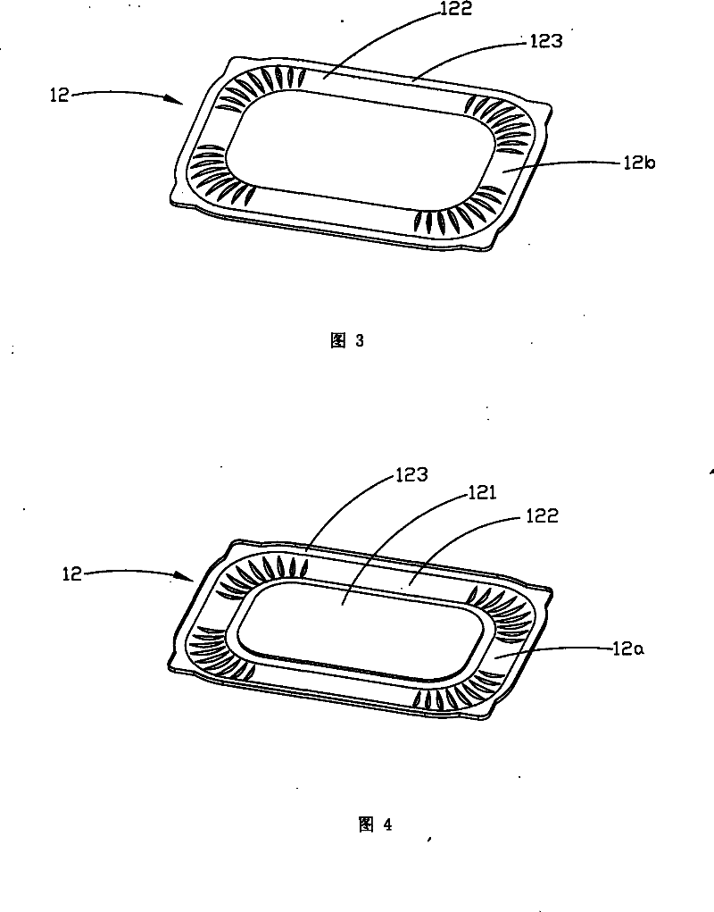
[0021] Among them, such as image 3 and 4 As shown, the diaphragm 12 includes a front surface 12a and ...


PUM


Abstract

The invention discloses a method for making a micro sounding device. The method comprises the following steps of: spreading a layer of hot melt glue on a limit frame of an upper cover; positioning a diaphragm positioning frame on the limit frame of the upper cover; heating the upper cover to melt the solidified hot melt glue and then cooling the upper cover to solidify the hot melt glue in order to adhere the peripheries of the upper cover and the diaphragm tightly. The method for making the micro sounding device makes the peripheries of the upper cover and the diaphragm tightly connected together, without causing the pollution of the glue to the diaphragm, thereby improving the performance of products.

Description

technical field [0001] The invention relates to a manufacturing method of a micro-sounding device, in particular to a process method for bonding the diaphragm of the micro-sounding device to the periphery of an upper cover. Background technique [0002] Miniature sound generating devices are widely used in portable electronic devices such as mobile phones and notebook computers. With the rapid development of these portable electronic devices, people's functional requirements are getting stronger and stronger, and the miniature sound-generating devices applied to them are also developing correspondingly and rapidly. [0003] Please refer to figure 1 , the micro-moving-coil sounding device 2 of related structure comprises a lower casing 21', an upper cover 26' connected to the lower casing 21' and provided with a sound hole 261', a magnetic bowl accommodated in the lower casing 21' 22', a diaphragm 25'. The front side of the diaphragm 25' and the upper cover form a front ca...

Claims


Application Information

Patent Timeline
Patent Type & Authority Patents(China)
IPC IPC(8): H04R31/00
Inventor 黄兴志周粉
Owner AAC ACOUSTIC TECH (CHANGZHOU)CO LTD
Why Eureka
Try Eureka