Clutch assistor for car

A clutch and booster technology, applied in clutches, mechanical equipment and other directions, can solve the problems of high manufacturing cost, low qualification rate, affecting the sealing of booster piston, etc., and achieve the effect of low manufacturing cost, high qualification rate and avoiding strain.

Inactive Publication Date: 2008-08-13
曾忠莉
View PDF0 Cites 9 Cited by
  • Summary
  • Abstract
  • Description
  • Claims
  • Application Information

AI Technical Summary

Problems solved by technology

[0003] The clutch booster of prior art mainly has following deficiencies (as shown in Figure 1): A, cylinder 2 endoporus wall wear resistance is poor, also has booster to spray on the cylinder inner wall, but powder coating produces uneven particle, easily will assist piston The sealing ring on 6 is strained, resulting in air leakage, which makes the push rod 7 weak; B. The push rod 7 is connected to the internal thread of the release fork 20, so that the total length of the push rod 7 and the release fork 20 can be adjusted, but when the clutch booster The flange is fixed on the gearbox bracket, and after the release fork is connected to the clutch rocker arm, if you want to adjust the length of the push rod, at least any fixed end of the booster must be removed, and then the push rod or release fork can be rotated to adjust the length. It is very inconvenient to adjust the length; C. The cylinder is a stamping part. Because the cylinder is a deep cylinder, it needs to be stretched many times, requiring large stamping equipment and multiple molds. The processing technology is complicated, the manufacturing cost is high and the pass rate is low. Not only the cylinder design length is limited And the cylinder band taper that stamping draws out, and surface roughness is low, influences the sealing of booster piston in the cylinder; Only one end of the cover is stuck on the edge of the

Method used


Image

  • Clutch assistor for car
  • Clutch assistor for car
  • Clutch assistor for car

Examples


Embodiment Construction

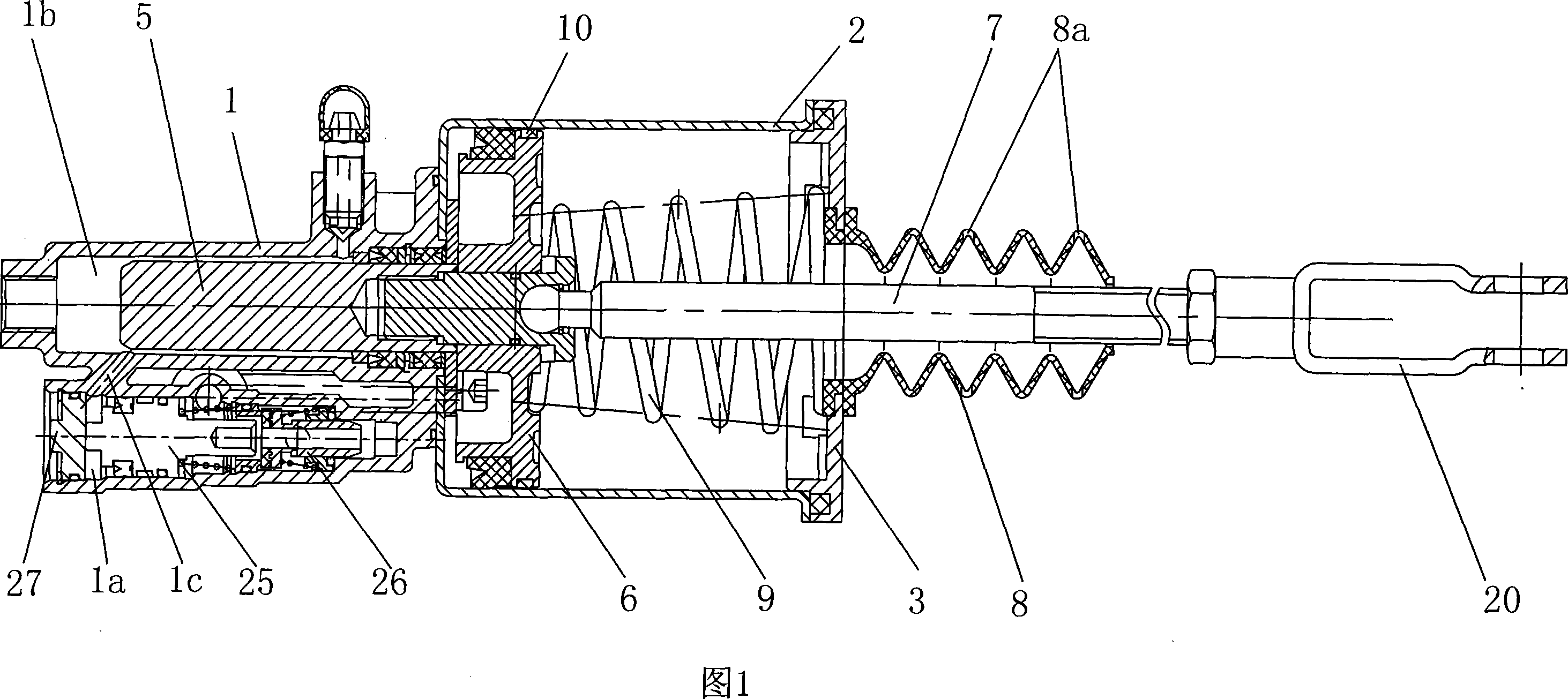
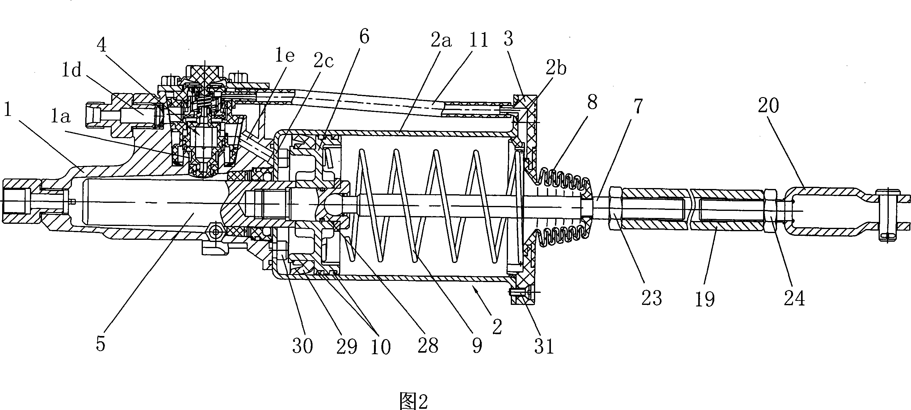
[0022] Below in conjunction with accompanying drawing and embodiment the present invention will be further described:

[0023] As shown in Figure 2, the present invention mainly consists of a cylinder shell 1, a cylinder 2, a flange 3, an air valve assembly 4, a cylinder piston 5, a booster piston 6, a push rod 7, a dust cover 8, a main spring 9, a damper Friction ring 10, air pipe 11, adjusting screw sleeve 19, separating fork 20, right-handed nut 23 and left-handed nut 24 form. Wherein the sealing end of cylinder shell 1 and cylinder 2 is fixed by bolt 30, and the front end of cylinder 2, that is, the open end, is connected with flange 3 by screw 31, and cylinder piston 5 is housed in cylinder 1b of cylinder shell 1, and the cylinder piston 5 One end extends into the cylinder 2 and is threadedly connected with the booster piston 6 through the connecting sleeve 28. A push rod 7 is fixed at the center of the front end of the booster piston 6, and the other end of the push rod ...


PUM

PropertyMeasurementUnit
Wall thicknessaaaaaaaaaa

Abstract

The present invention provides an auto clutch booster, including an oil cylinder case and a cylinder fixed on the front of the oil cylinder case, the front of the cylinder is a ring flange, a valve chamber extending outwards is set at the middle and front of the oil cylinder case, gas valve assembly is packed in the valve chamer, the inner wall of the cylinder is plated with hard chrome layer, concave grooves are set on two sides of the boosting pistion; the front of the pushing rod is covered with adjusting threaded sleeve via right-hand threaded sleeve, the other end of the adjusting threaded sleeve is connected with the separating fork via minus screw, the pushing rod and the separating fork of the adjusting screw sleeve are covered with right-hand screw and the left-hand screw respectively. The cylinder of the invention has a better wear resistance, easy process, lower manufacturing cost; the booster can conveniently quick adjust the length of the pushing rod and the separating fork un-detachably after being mounted on the body; the cylinder also effectively dustproof, avoiding strain, jammed and invalid of cylinder and gas valve caused by dust inlet; the mounting position of the ring flange is adjusted, having better popularity.

Description

technical field [0001] The invention relates to an automobile clutch booster, in particular to an automobile clutch booster which is hydraulically controlled and boosted by compressed air. Background technique [0002] In order to reduce the labor intensity of the driver in manipulating the clutch and ensure driving safety, clutch boosters are commonly used on medium and heavy vehicles. The automobile clutch booster is a key component to ensure the safety of the car. When the clutch pedal is stepped on, the hydraulic oil pressed from the clutch master cylinder enters the cylinder of the booster through the oil pipe, as shown in Figure 1. Under the action of the hydraulic oil, The cylinder piston 5 can only push the booster piston 6 in the cylinder 2 to move forward a little distance, and at the same time, the hydraulic oil enters the oil chamber at the rear end of the valve assembly 4 in the valve chamber 1a through the communication pipe 1c in the cylinder shell 1, and the ...

Claims


Application Information

Patent Timeline
IPC IPC(8): F16D48/04
Inventor 曾忠莉陈学武曾金
Owner 曾忠莉
Why Eureka
Try Eureka