Clutch to clutch tie-up steady-state diagnostic

A state, transmission technology, applied to elements with teeth, transmission control, belt/chain/gear, etc., can solve the problem of false detection of standstill, vibration or other phenomena

Active Publication Date: 2008-08-13
GM GLOBAL TECH OPERATIONS LLC
View PDF0 Cites 3 Cited by
  • Summary
  • Abstract
  • Description
  • Claims
  • Application Information

AI Technical Summary

Problems solved by technology

However, the conventional diagnostic procedure described may result in false detection of a

Method used


Image

  • Clutch to clutch tie-up steady-state diagnostic
  • Clutch to clutch tie-up steady-state diagnostic
  • Clutch to clutch tie-up steady-state diagnostic

Examples


Embodiment Construction

[0016] The following specific examples are merely exemplary in nature and are in no way intended to limit the invention, its application or uses. For purposes of clarity, the same reference numbers refer to the same elements. As used herein, the term module refers to an application-specific integrated circuit (ASIC), electronic circuit, processor (shared, dedicated, or combined) and memory executing one or more software or firmware programs, combinational logic circuits, or other suitable parts.

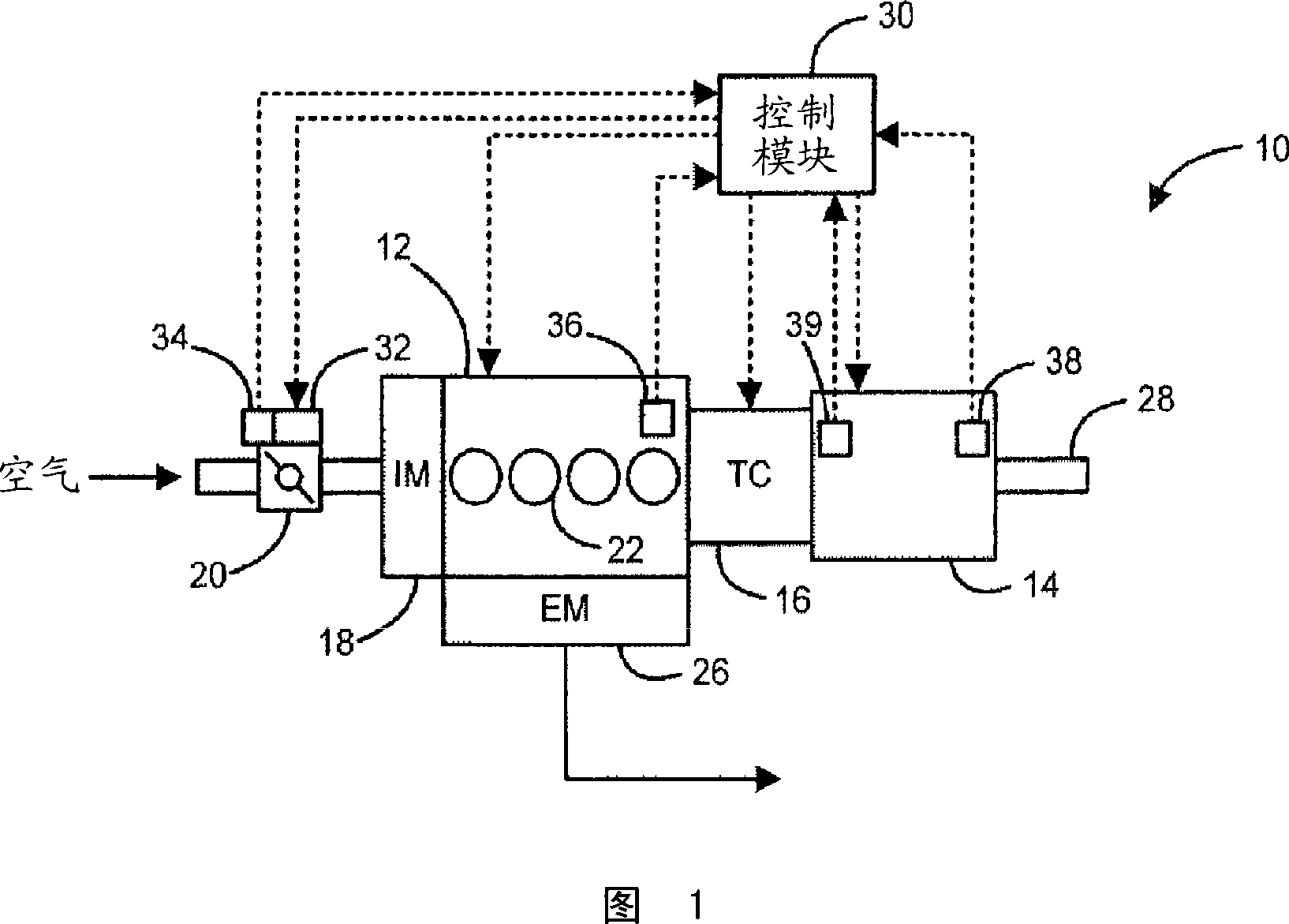
[0017] Referring now to FIG. 1 , an exemplary powertrain system 10 is illustrated and includes an engine 12 driving a transmission 14 through a coupling 16 . More specifically, air is drawn into the intake manifold 18 of the engine 12 through the throttle valve 20 . The air is mixed with fuel, and the air / fuel mixture is combusted within cylinders 22 to drive pistons (not shown) in reverse within cylinders 22 . The pistons rotatably drive a crankshaft (not shown) to provide drive ...


PUM


Abstract

The present invention relates to a method of regulating operation of an automatic transmission comprising identifying a standstill condition of the automatic transmission, adjusting transmission element pressures in response to the standstill condition and determining whether to maintain a first gear ratio of the automatic transmission. If the gear ratio is not maintained and the faulty transmission element is determined to be the one associated with a second gear ratio lower than said first gear ratio, the pressure is set to zero.

Description

technical field [0001] The disclosure herein relates to a prime driven transmission, and more particularly to clutch control of a transmission identifying a clutch causing a standstill condition. Background technique [0002] The statements in this section merely provide background information related to the disclosure and may not constitute prior art. [0003] Traditionally, vehicles include an active power source, such as an internal combustion engine, that generates drive torque. The drive torque is transmitted to the drive system through the power system to propel the vehicle along the ground. Exemplary powertrain components include a transmission and a coupling device through which drive torque is transferred from the engine to the transmission. The transmission increases the drive torque via the gear ratio and further transmits the increased drive torque into the drive train. [0004] Exemplary transmissions include automatic transmissions having a plurality of tran...

Claims


Application Information

Patent Timeline
IPC IPC(8): F16H61/00F16H61/12
CPCF16H61/12F16H2061/1204Y10S477/906
Inventor T·J·索尔
Owner GM GLOBAL TECH OPERATIONS LLC
Why Eureka
Try Eureka