Intensified heat transfer pipe

A heat transfer tube and tube body technology, applied in the field of enhanced heat transfer tubes, can solve problems that have not yet been seen, and achieve the effects of improving heat transfer coefficient, strengthening condensation heat transfer, and increasing the number

Active Publication Date: 2008-08-13
JIANGSU CUILONG PRECISION COPPER TUBE CORP
View PDF9 Cites 5 Cited by
  • Summary
  • Abstract
  • Description
  • Claims
  • Application Information

AI Technical Summary

Problems solved by technology

[0006] However, there has not been seen in the published literature that the structure of the outer fins outside the heat exchange tubes of the evaporator and condenser can reflect the technical inspiration of significantly improving the heat coefficient of phase transformation

Method used


Image

  • Intensified heat transfer pipe
  • Intensified heat transfer pipe
  • Intensified heat transfer pipe

Examples


Embodiment 1

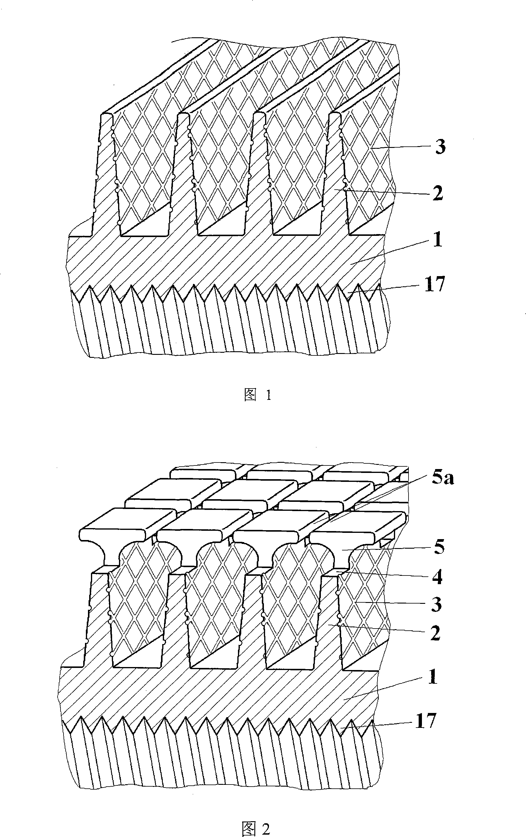
[0029] Please see Fig. 1, the outer fin 2 is formed and rolled on the outer wall of the tube body 1 with the inner fin 17 at one time, and a kind of enhanced heat transfer tube is produced. The outer fin 2 is made of the material on the tube body 1 along the tube The body 1 is formed by extending outward in the radial direction, and is an integral structure with the pipe body 1. There is a contact thermal resistance between them. The outer fins 2 extend spirally around the pipe body 1 on the outer surface of the pipe body 1; At the same time as the outer fins 2, dense micro-scale grooves 3 are processed on the side surface of the outer fins 2 by a cutter. These micro-scale grooves 3 are micro-scale groove slotting knives 9 (shown in Figures 3 and 4) A cluster of dense curves is drawn when the outer fin 2 is rotated relative to the outer fin 2. On both sides of the outer fin 2, the cluster of curves forms a grid-like structure. The micro-scale channels 3 of the grid-like structu...

Embodiment 2

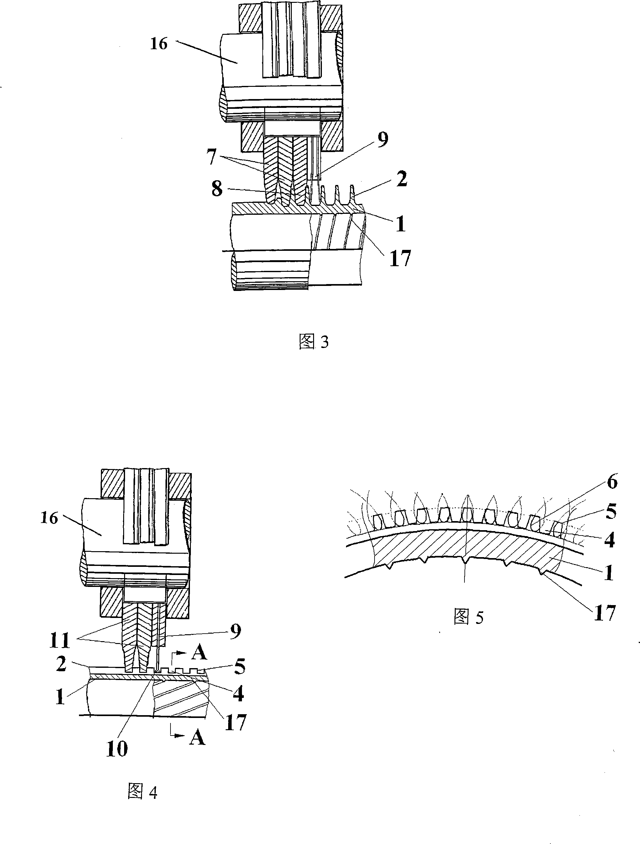
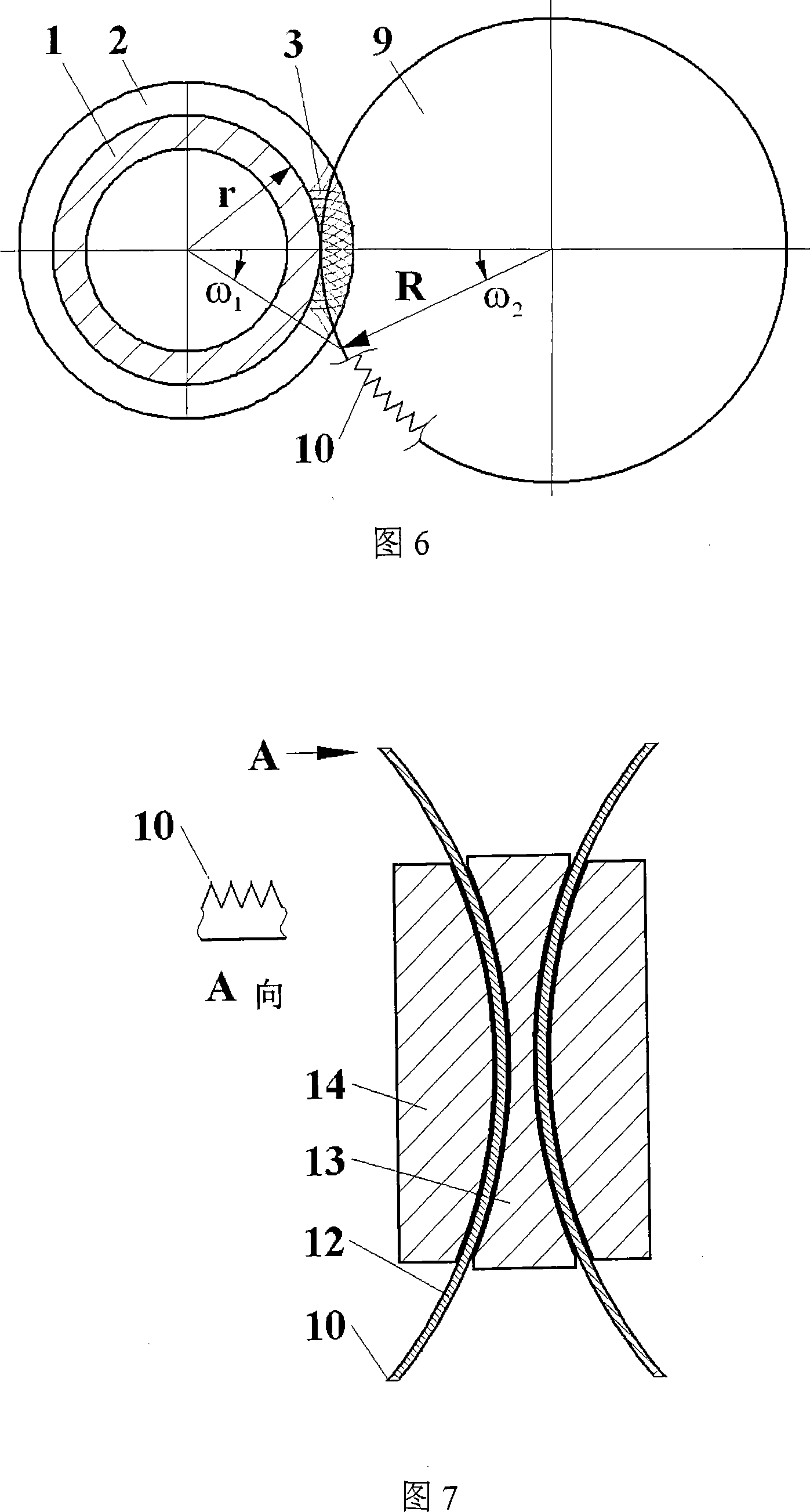
[0033]Please see Fig. 3 and Fig. 6, equipped with outer fin grooving knife 7, outer fin forming knife 8 and micro-scale channel grooving knife 9, and install this group of cutters on the tool holder 16 (also called cutter shaft) Above, among them, the edge of the micro-scale channel slotting knife 9 is uniformly provided with a plurality of knife edges 10 (shown in Figure 6), and the outer fin 2 is processed and formed on the tube body 1 by extrusion method at one time, and the typical size is The diameter of the tube body 1 at the root of the outer fin 2 is 20mm. During the relative rotation between the tube body 1 and the above-mentioned cutter, the outer fin 2 with a height of 2mm is formed by the outer fin slotting knife 7 and the outer fin forming knife 8, and at the same time, the micro-scale channel slotting knife 9 The knife edge 10 (shown in FIG. 6 ) marks regular micro-scale grooves 3 with a groove width of 0.08 mm, a groove depth of 0.05 mm, and an average groove di...

Embodiment 3

[0047] Please refer to FIG. 4 and FIG. 5 in conjunction with FIG. 2 , taking the example of making the enhanced heat transfer tube of the present invention used as a condensation tube and shown in FIG. 2 .

[0048] The specific structure includes a tube body 1, an outer fin 2 formed on the outer wall of the tube body 1, a groove 4 is cut out on the outer fin 2, a tooth platform 5 is formed between two adjacent grooves 4, and the groove 4 The depth of the outer fin 2 is less than the height of the outer fin 2. The groove 4 and the tooth platform 5 form the outer fin 2 in a zigzag shape. There are 1 to 2 lines on the surface of the tooth platform 5 opposite to the groove 4 from the root of the tooth platform 5 to the top. Extended arc-shaped micro-scale channels 6 (shown in Figure 5) and micro-scale channels 3 are formed on the side surfaces of both sides of the outer fin 2. The groove width of the scale channel 3 and the arc-shaped micro-scale channel 6 are 0.05mm and 0.01mm re...


PUM


Abstract

A strengthening heat-conducting pipe is provided, belonging to the field of heat exchanging component. The invention comprises a pipe body and an outer wing sheet integrated with the pipe body which extends along the radius direction of the pipe body and extends spirally around the surface of the pipe body. At least one side of lateral surface of the outer wing sheet configures micro-scale groove channel. The advantages are flowing: because at least one side of lateral surface of the outer wing sheet configures micro-scale groove channel, it is beneficial to increase heat-exchanging area of surface of the outer wing sheet to enhance perturbation for the liquid, so that outer pipe compulsive convection heat exchange is strengthened and heat-conducting coefficient is improved. When the compulsive heat-conducting pipe of this invention is used for evaporator, the micro-scale groove channel can increase number of the gasified core and strengthen the boiled heat exchange under the situation of low-heat dense; when the compulsive heat-conducting pipe of this invention is used for condensator, the micro-scale groove channel can enhance distribution of the liquid film thickness of the outer wing sheet.

Description

technical field [0001] The invention relates to an enhanced heat transfer tube, which is used as a heat exchange component of an evaporator and a condenser in a refrigeration and air-conditioning system, and belongs to the technical field of heat exchange components. Background technique [0002] In the fields of refrigeration, air conditioning, process engineering, petrochemical industry, and energy and power engineering, etc., the boiling or condensation of liquid on the outer surface of the tube bundle is involved. Especially for evaporators and condensers used in refrigeration and air-conditioning systems, the thermal resistance of phase change when the refrigerant boils or condenses outside the tube is equivalent to or even greater than the thermal resistance of forced convection heat transfer inside the tube. Therefore, strengthening the phase change heat outside the tube can play a significant role in improving the heat transfer performance of the evaporator and conde...

Claims


Application Information

Patent Timeline
Patent Type & Authority Applications(China)
IPC IPC(8): F28F1/42
Inventor 陆明华张春明罗行周浩平
Owner JIANGSU CUILONG PRECISION COPPER TUBE CORP
Why Eureka
Try Eureka