

Imprint coating of thin film printing material
A thin film and coating technology, which is applied in the direction of transfer printing, printing of special varieties of printed matter, post-processing of printing, etc., can solve the problems of difficult operation and non-disclosure of coating, and achieve the effect of reducing matching distortion
- Summary
- Abstract
- Description
- Claims
- Application Information
AI Technical Summary
Problems solved by technology
Method used
Image

Examples
Embodiment Construction
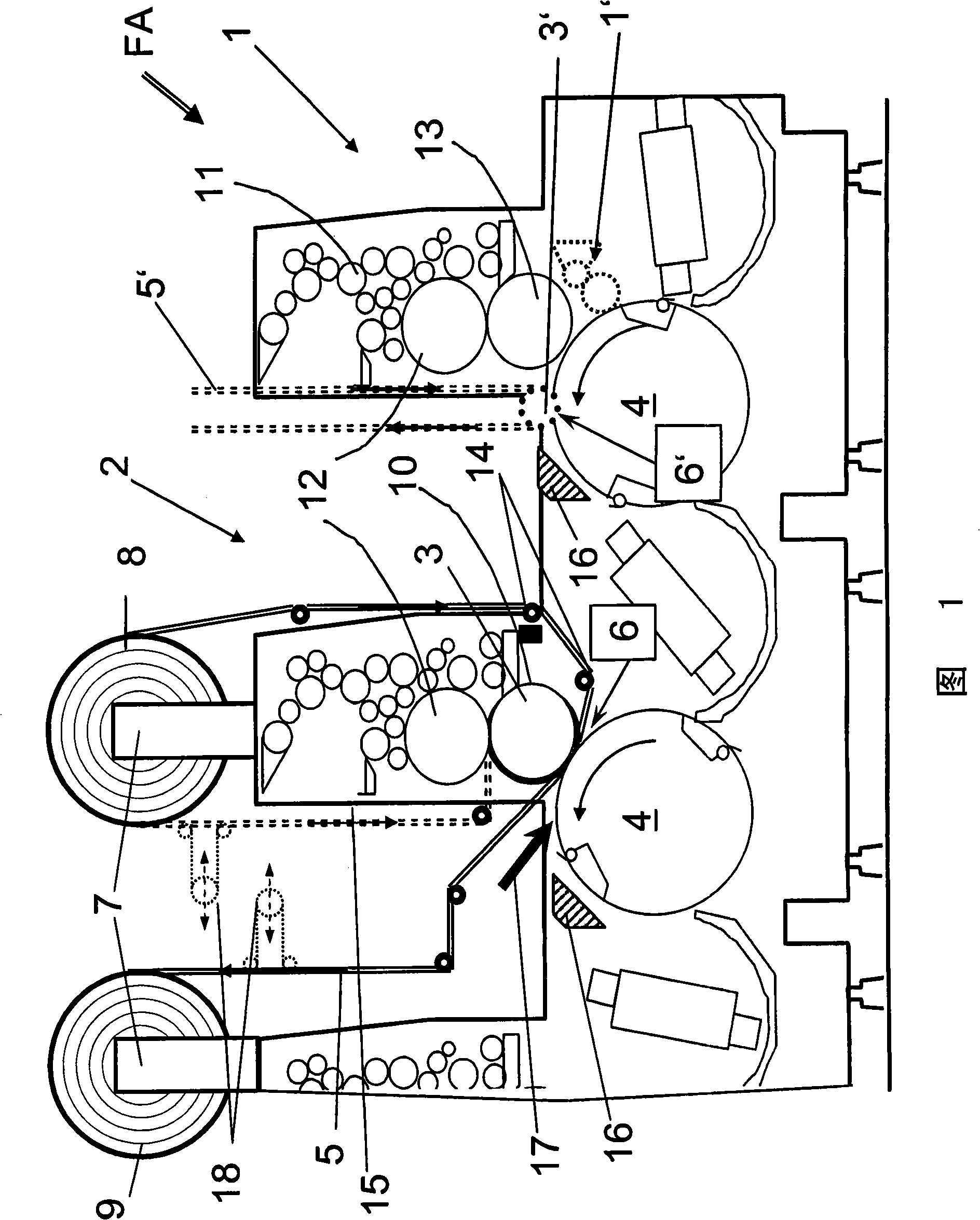
[0048] Figure 1 shows components of a sheet rotary printing press comprising two printing units and serving the following purposes:
[0049] - A printed sheet is initially provided with a flat or imaged adhesive pattern (printing unit as coating unit 1 ).
[0050] On the subsequent printing unit, the printed sheet is guided under pressure together with a transfer film 5 through a transfer nip 6 (coating unit 2 ).
[0051] The coating unit 1 can be an offset printing unit known per se, having an inking unit 11 , a printing form cylinder 12 and a printing cylinder 13 . The printing cylinder 13 cooperates with a counterpress cylinder 14 .
[0052] The coating unit 2 can likewise be formed by an offset printing unit. The transfer nip 6 in the coating unit 2 is formed by a pressure roller 3 and a counter-press roller 4 . The press roll 3 may correspond to a counter press roll. The pressure roller 3 can also correspond to the printing form cylinder of a painting unit. Inside th...
PUM
 Abstract
Description
Claims
Application Information