Cavity filter frequency adjustment mechanism

A cavity filter and frequency adjustment technology, which is applied in the direction of waveguide devices, resonators, electrical components, etc., can solve the problems of the connecting rod b and the cover plate being seized, the end is easy to deviate from the axis line, and the use effect is affected. , to achieve the effect of facilitating assembly, reducing processing procedures, and reducing processing accuracy requirements

Active Publication Date: 2008-08-20
SHENZHEN GRENTECH RF COMM LTD
View PDF1 Cites 4 Cited by
  • Summary
  • Abstract
  • Description
  • Claims
  • Application Information

AI Technical Summary

Problems solved by technology

Therefore, the requirements for the axial degree of the processing of the connecting rod b are relatively high in manufacturing. Even so, the end of the connecting rod b is still easy to deviate from the axis line during operation, which will cause the screw of the motor d and the connecting rod b, and the connecting rod b and the Seizure between cover plates a
Moreover, in the above structure, according to the requirements of use, the connecting rod b cannot be made of metal materials, and requires low dielectric constant, low loss and certain rigidity. Therefore, when the cavity height of the cavity filter is relatively large, the connecting rod b needs to use hollow thin-walled components, so the rigidity of the connecting rod b in the above structure is poor, and there is no good practicability
In addition, since the connecting rod b is driven to rotate by the motor d connected to its lower end, when moving close to the motor d, it needs to rely on the rebound force of the spring f set at the upper end to realize its adjustment. When the length of the connecting rod b is relatively large, This kind of feedback will produce hysteresis, affect the use effect, and the adjustment range is very small

Method used


Image

  • Cavity filter frequency adjustment mechanism
  • Cavity filter frequency adjustment mechanism
  • Cavity filter frequency adjustment mechanism

Examples


Embodiment 1

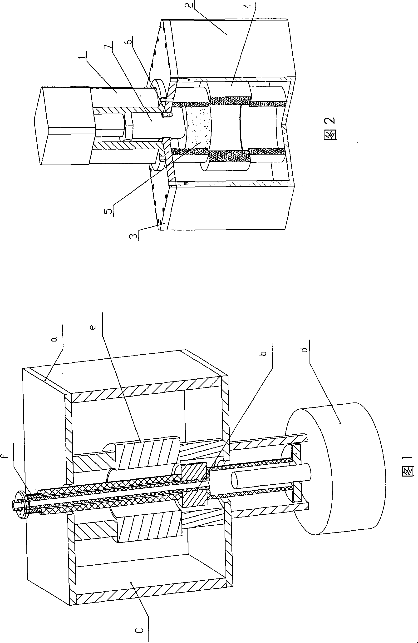
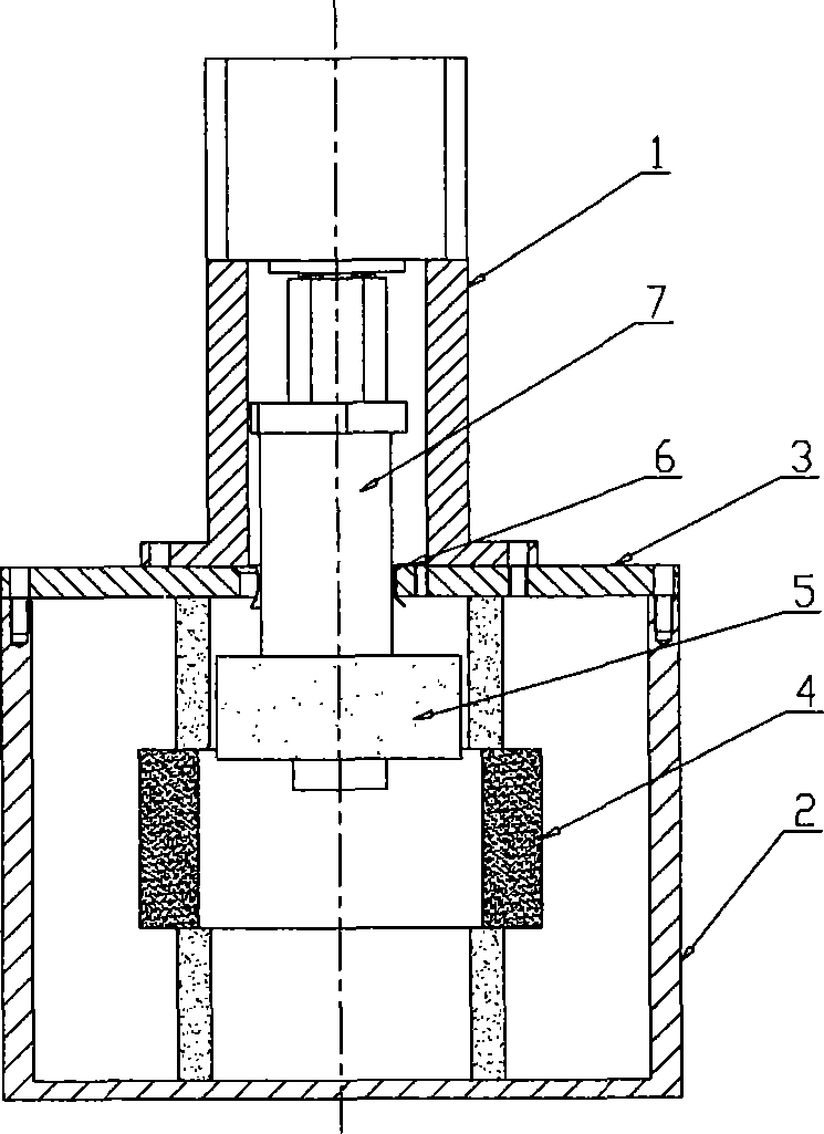
[0042] Figure 2~ Figure 4 As shown, the present invention includes: a cavity body 2, an inner dielectric body 5, an outer dielectric body 4 and a connecting rod 7, the cavity body 2 is a thin-walled cylinder structure, and the outer dielectric body 4 is also A cylindrical structure with an inner cavity machined in the center is fixedly placed in the center of the inner cavity of the cavity body 2, and the center line of the two must be guaranteed to be within a certain tolerance range during assembly. The connecting rod 7 is placed in the inner cavity of the cavity body 2 and is connected with the transmission device 1, wherein the transmission device 1 includes a motor (not shown in the figure) and a leading screw 8, and the leading screw 8 is connected with the connecting rod 7. Driven by the motor, the connecting rod 7 can be moved axially in the inner cavity of the cavity body 2 through the lead screw 8 . The inner dielectric body 5 is installed on the connecting rod 7 a...

Embodiment 2

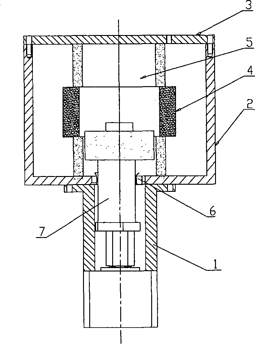
[0047] Such as Figure 3a As shown, the composition and coordination of the parts of this embodiment are the same as those of the first embodiment, the cover plate 3 is installed on the cavity body 2, the difference is that the transmission device 1, the clamping device 6, the connecting rod 7, etc. are all inverted At the bottom of the cavity body 2, the tightening device 6 is set in the corresponding groove on the bottom end of the cavity body 2, which cooperates with the working surface 7.1 of the connecting rod, and can also realize the automatic centering function of the connecting rod 7 .

Embodiment approach

[0049] As shown in Figure 2, image 3 As shown, the transmission device 1 connected to the connecting rod 7 of the present invention is fixed on the cavity body 2 or placed on the cover plate 3 provided on the cavity body 2, and the connecting rod 7 is placed on the transmission device 1. Therefore, the clamping device 6 can also be set in the groove corresponding to the transmission device 1, and it can cooperate with the working surface 7.1 of the connecting rod to realize the automatic movement of the connecting rod 7. Centering function. This can be the fourth embodiment of the arrangement of the tightening device of the present invention.

[0050] In the above-mentioned structural embodiments, the part of the tightening device 6 of the present invention that is in contact with the working surface 7.1 of the connecting rod and the part that is in contact with the inner wall of the groove cavity can also be combined by two components, wherein the part that is in contact wit...


PUM


Abstract

The present invention provides a frequency governing mechanism for cavum filter, which comprises of cavum body, inner and outer medium and connecting rod moved by gearing. The outer medium is placed in cavum body, the connecting rod is placed in outer medium, and the inner medium is mounted on connecting rod. Wherein, a stretch device capable of making connecting rod, inner medium axes and cavum body or / and outer medium concentric automatically is set on the connecting rod. The stretch device can be set in corresponding groove of cavum body, cover board or gearing, which comprises of at leasttwo elastic members symmetric to center of vacuum, the front end of each member has stretch working surface matched to connecting rod, the rear end is arc surface capable of swing automatically alonginner wall of groove and stretched touch with inner wall of groove. A pair of elastic double nuts space adjusting member is set on the lead screw. The present invention can eliminate assembly error, ensure the motor lead screw, connecting rod, vacuum body, inner or outer medium and cover board is concentric, improve the rigidity of connecting rod.

Description

【Technical field】 [0001] The invention relates to the technical field of cavity filters in base stations of mobile communication systems, in particular to a tuning mechanism for automatically tuning the frequency relationship of the filter and / or the coupling efficiency factor between central conductors in the filter. 【Background technique】 [0002] The cavity filter is one of the common components in the mobile communication system. Due to the manufacturing errors of the parts that make up the cavity filter, it must be assembled through adjustment. There are many kinds of tuning mechanisms for cavity filters, such as ordinary screw tuning mechanisms, self-locking screw tuning mechanisms, and automatic tuning mechanisms. [0003] US 6255922 B1 patent has disclosed an automatic tuning mechanism for a cavity filter, as shown in Figure 1, the cavity filter includes a cavity closed by a cover plate a, and the connecting rod b passes through the entire cavity Body c, the lower e...

Claims


Application Information

Patent Timeline
IPC IPC(8): H01P7/10H01P1/207
Inventor 解波肖利蒙
Owner SHENZHEN GRENTECH RF COMM LTD
Why Eureka
Try Eureka