Spectrograph-based optical displacement sensor signal demodulation method

A displacement sensor and signal demodulation technology, used in instruments, optical devices, measuring devices, etc., can solve the problems of incident light incident angle deviation, erroneous displacement information, increasing difficulty in calculation and solution, and eliminate processing and assembly errors. , the effect of improving calculation accuracy and shortening data processing time

Active Publication Date: 2014-05-21
FLIGHT AUTOMATIC CONTROL RES INST
View PDF2 Cites 2 Cited by
  • Summary
  • Abstract
  • Description
  • Claims
  • Application Information

AI Technical Summary

Problems solved by technology

[0003] Due to the limitations of the current grating manufacturing process, the grating density equation is an approximate cubic distribution, which makes the calculation and solution of step (3) more difficult and the processing time increases; at the same time, errors in processing and assembly cause deviations in the incident light angle, resulting in the diffraction formula The calculation result does not match the actual, and the solution calculates the wrong displacement information

Method used


Image

  • Spectrograph-based optical displacement sensor signal demodulation method
  • Spectrograph-based optical displacement sensor signal demodulation method
  • Spectrograph-based optical displacement sensor signal demodulation method

Examples


Embodiment

[0025] Step 1: The optical displacement sensor outputs a narrow-band diffracted light signal to the spectrometer;

[0026] Step 2: The spectrometer selects the HR4000 type of Haiyang Company to read the spectral information of the narrow-band diffracted light;

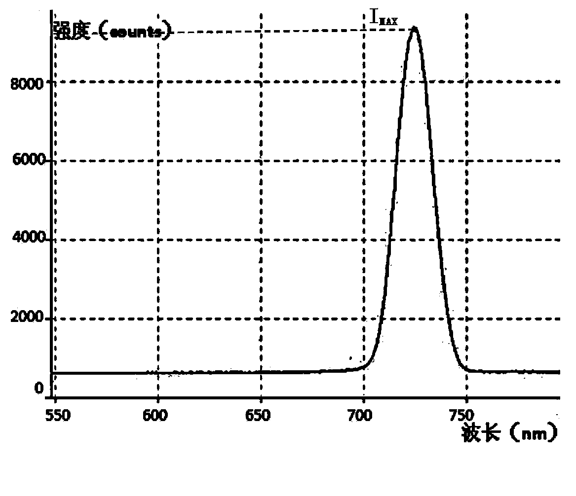
[0027] Step 3: The spectrometer inputs the corresponding array data of wavelength λ and light intensity I in the spectral information to the computer. The corresponding arrays of wavelength λ and light intensity I are two arrays containing 3648 values. The typical corresponding relationship is as follows figure 2 shown;

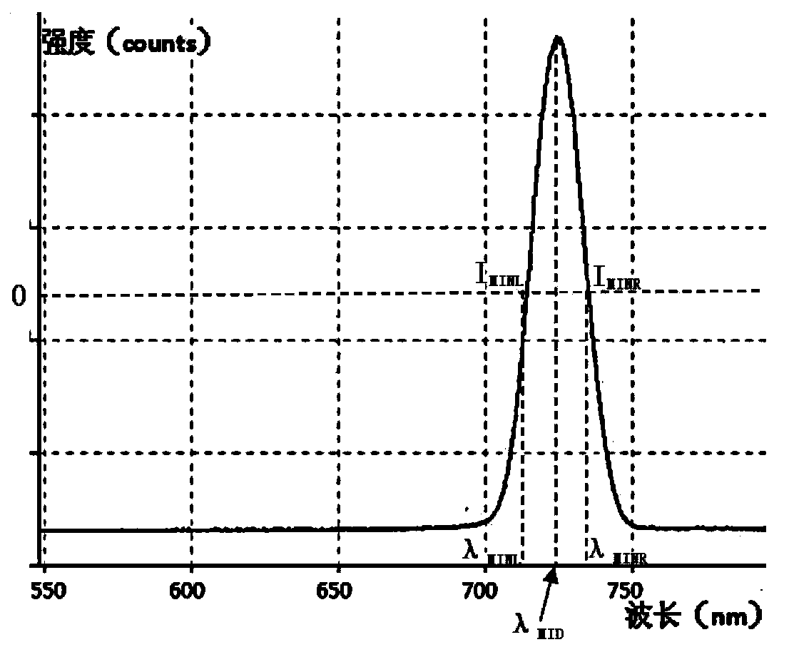
[0028] Step 4: The computer processes the corresponding array data of the wavelength λ and the light intensity I by using the half-height width method, and obtains the central wavelength λ of the narrow-band diffracted light 0 . First use the point-by-point comparison method to obtain the maximum value I of the light intensity I MAX , its light intensity value is 9144; after that, the correspondin...


PUM


Abstract

The invention relates to a spectrograph-based optical displacement sensor signal demodulation method. According the scheme, a data processing process of a wavelength encoding type optical displacement sensor comprises (1) reading spectroscopic data of output diffraction light of the sensor through a spectrograph; (2) processing the data through a full width at half maximum peak searching algorithm to obtain central wavelength; (3) performing comprehensive regression interpolation on the central wavelength to obtain displacement information. The spectrograph-based optical displacement sensor signal demodulation method has the advantages of being rapid, not needing a gate code calculation process and shortening data processing time; being accurate, avoiding gate code equation fitting errors and improving the calculation accuracy; being independent, not being influenced by optical grating diffraction angle errors and eliminating machining and assembling errors due to the facts that a former process of obtaining the grate code through a diffraction formula is eliminated and the displacement is directly obtained through the central wavelength.

Description

technical field [0001] The invention relates to a signal demodulation method of an optical displacement sensor based on a spectrometer. Background technique [0002] With the development of optical transmission flight control technology, the research of optical displacement sensor is deepening continuously, and the processing of output signal of optical displacement sensor has become the research focus. In the development of wavelength coded optical displacement sensor, the core data processing is determined by wavelength Calculate the displacement information of the sensor, the processing flow is: (1) The spectrometer reads the spectral data of the output diffracted light of the sensor; (2) Process the data through the algorithm to obtain the central wavelength; (3) Obtain the grating density through the diffraction formula; ( 4) Calculate the displacement through the grating density equation. [0003] Due to the limitations of the current grating manufacturing process, th...

Claims


Application Information

Patent Timeline
IPC IPC(8): G01B11/02
Inventor 李秉实张兵王东辉包艳吴忠
Owner FLIGHT AUTOMATIC CONTROL RES INST
Why Eureka
Try Eureka