
Miniaturized ultra-wideband antenna with dual-attenuation band function

An ultra-wideband antenna and double stopband technology, which is applied in the direction of antenna, resonant antenna, and mid-position feed between antenna endpoints, can solve the problems of not being able to completely filter out interference, increase antenna volume and cost, etc.

Inactive Publication Date: 2008-08-20
SOUTHEAST UNIV
View PDF0 Cites 11 Cited by
  • Summary
  • Abstract
  • Description
  • Claims
  • Application Information

AI Technical Summary

Problems solved by technology

The more commonly used method is to add a filter at the rear end of the antenna or design multiple antennas working in different frequency bands to form stop bands with each other to achieve the function of filtering out interference frequency band signals, but this increases the size and cost of the antenna; another method By loading a V or U-shaped slit on the radiating element of the antenna to change the current distribution on the surface of the radiating element to achieve the band-stop function, but this usually only provides a stop band and cannot completely filter out potential interference

Method used


Image

  • Miniaturized ultra-wideband antenna with dual-attenuation band function
  • Miniaturized ultra-wideband antenna with dual-attenuation band function
  • Miniaturized ultra-wideband antenna with dual-attenuation band function

Examples


Embodiment Construction

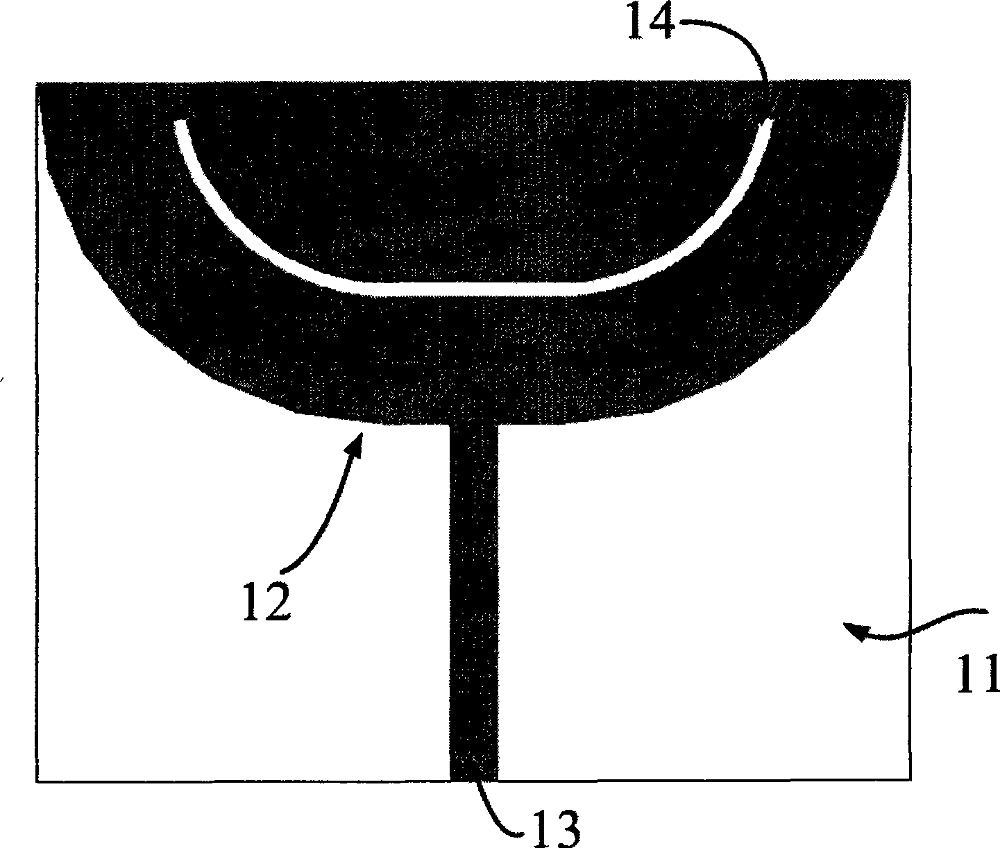
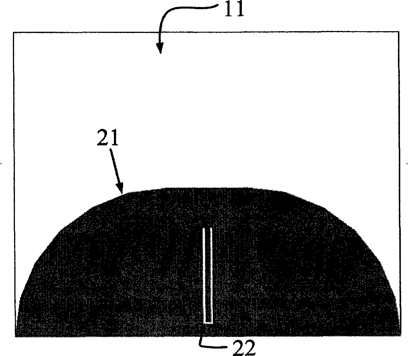
[0016] The antenna includes a dielectric substrate and plane metal printed on both sides of the dielectric substrate, one side is attached with a metal layer as a radiation unit and a microstrip feeder, and the other side is attached with a metal layer as a floor. An arc-shaped gap is etched on the metal layer of the radiation unit, and a U-shaped defect ground structure (DGS) is etched in the center of the floor metal layer on the other side. The radiation unit is connected to the microstrip line, and the end of the microstrip line is connected to an SMA head to facilitate connection with other systems.

[0017] The radiation unit of the antenna is composed of two quarter circles and a rectangle. In order to achieve ultra-wideband, the floor of the antenna adopts the same and symmetrical structure as the radiation unit. This gradual symmetrical structure ensures that the antenna can work in the FCC The specified ultra-wideband frequency band and has a small volume.

[0018] ...


PUM


Abstract

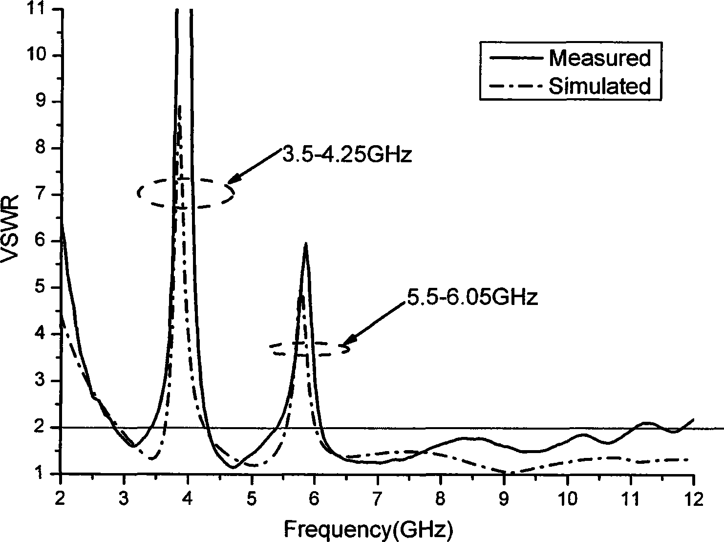
Ultra-wideband antenna with dual stopband capability can resolve efficiently problem that ultra-wideband communication system is disturbed by signal of narrowband communication system, one side adhesion of medium substrate is as metal layer of radiation cell and microstrip feeder, the other side adhesion is as metal layer of floor, radiation cell is a semicircle metal slice, microstrip and radiation cell are connected. Floor has symmetrical shape with radiation cell and lies on the back of microstrip feeder. Arc gap is set on radiation cell and U-shaped gap is etched on floor. The present invention can realize dual stopband capability at a certain working range (3.1GHz-10.6GHz) to filter disturb to ultra-wideband system by other latent narrowband system.

Description

technical field [0001] The antenna of the invention can effectively solve the problem that the ultra-wideband communication system is interfered by signals of other existing narrow-band communication systems, and in particular relates to an ultra-wideband antenna with double stopband characteristics, which belongs to the technical field of communication. Background technique [0002] Ultra-wideband communication (UWB) is a wireless interconnection technology that has emerged in the field of communication in recent years. It is used to realize wireless transmission within a short distance of 10m. It has the characteristics of high data rate, low power consumption, simple structure and low price. . The U.S. Communications Commission (Federal Communications Commission, FCC) allocated the 3.1 GHz-10.6 GHz frequency band in 2002 as a usable frequency band for the UWB system. [0003] The characteristics and rapid development of UWB make the design of UWB antenna a hot spot in th...

Claims


Application Information

Patent Timeline
IPC IPC(8): H01Q1/38H01Q13/08H01Q9/16
Inventor 徐金平殷康赵亚辉
Owner SOUTHEAST UNIV
Learn More