Handling device for elements of tapping runners

A technology for processing devices and tapping troughs, which is applied to discharge devices, blast furnace parts, furnace components, etc., and can solve problems such as difficult parking positions and bulky structures

Inactive Publication Date: 2008-08-20
TMT TAPPING MEASURING TECH
View PDF4 Cites 3 Cited by
  • Summary
  • Abstract
  • Description
  • Claims
  • Application Information

AI Technical Summary

Problems solved by technology

Parking positions that are achievable with prior art devices are often not readily available due to the limited space available
Furthermore, prior art devices have a bulky construction and often require attachment to a fixed structure above the casthouse floor

Method used


Image

  • Handling device for elements of tapping runners
  • Handling device for elements of tapping runners
  • Handling device for elements of tapping runners

Examples


Embodiment Construction

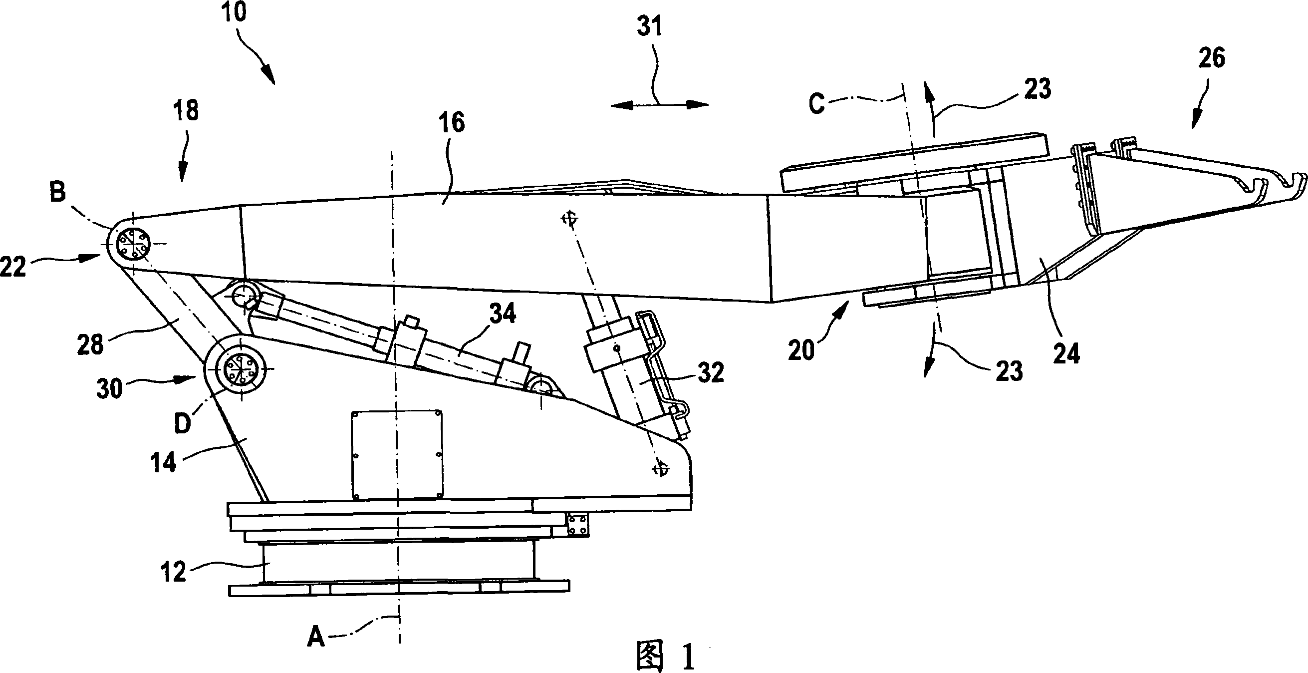
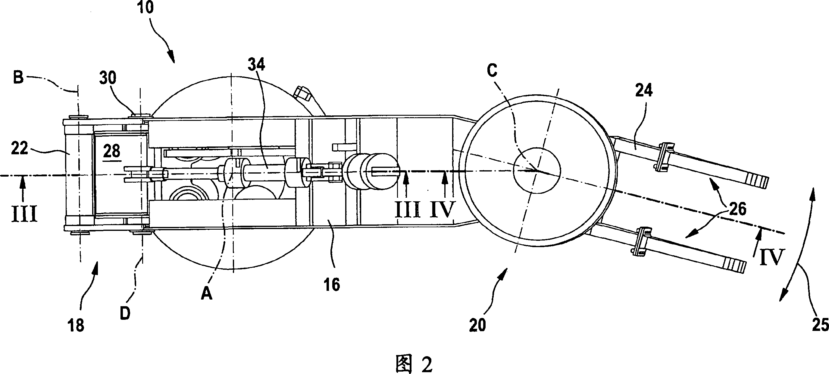
[0031]1 and 2 show a processing device generally indicated by reference numeral 10 . The handling device 10 includes a support base 12 and a frame 14 . The supporting base 12 is secured by suitable means to the casthouse floor and provides a stable support for the handling device 10 . The frame 14 is connected to the support base 12 by bearings (described in detail below) providing a first axis of rotation A, which is substantially vertical. Thus, the frame 14 is supported by the support base 12 and is rotatable about the axis A relative to the support base. It will be appreciated that the support base 12 and frame 14 may be configured to allow substantially 360° rotation. However, the range of rotation can be limited according to structural requirements, for example to prevent collisions with fixed structures. The handling device 10 further includes a lift arm 16 having a first end 18 and an opposite second end 20 . The first end 18 of the lift arm 16 is connected to the ...


PUM


Abstract

A handling device for elements of tapping runners on a shaft furnace, in particular for runner covers, the device including a support base arranged on the cast house floor of a blast furnace, laterally of the tapping runner and a frame ( 14 ) which is supported by the support base and connected thereto by means of a bearing defining a first axis of rotation, which is essentially vertical and about which the frame can rotate relative to the support base. The device further includes a lifting arm having a first end portion and a second end portion, the first end portion being connected to the frame by means of at least a first rotational joint defining a second axis of rotation, which is essentially horizontal, about which the lifting arm can pivot in order to lower or lift its second end portion. A handling member is connected to the second end portion of the lifting arm by means of a second rotational joint defining a third axis of rotation, which lies in a plane essentially perpendicular to the second axis of rotation, about which the handling member can pivot with respect to the lifting arm. Furthermore, the handling device includes a fork-type grab connected to the handling member and arranged so as to allow picking up; transferring and putting down such elements.

Description

technical field [0001] The present invention relates to a treatment device for tapping chute parts located on a shaft furnace, in particular to a treatment device for the main trough cover of a blast furnace. Background technique [0002] In order to reduce harmful jets and heat radiation in the casthouse of a blast furnace, it is known to cover the tapping trough (also called launder or trough) with at least one moving cover part. Such a tapping spout cover comprises an elongated metal shell fitted with an inner refractory protection. Their dimensions may be several meters long and several meters wide. They can weigh well over 10,000kg. [0003] However, in order to tap the taphole and block the taphole, the upstream taphole cover (ie, the taphole cover directly downstream of the taphole) must be removed. The upstream tapping spout cover is usually placed in the parking position and then pushed back in front of the tapping hole. Such handling operations cannot be conven...

Claims


Application Information

Patent Timeline
Patent Type & Authority Applications(China)
IPC IPC(8): F27D3/14F27D99/00
CPCC21B7/14F27D3/14F27D3/145C21B7/00
Inventor 罗伯特·戈尔扎汉斯-奥托·克罗伊茨拉尔夫·陶格尔贝克
Owner TMT TAPPING MEASURING TECH
Why Eureka
Try Eureka