Signal source device

A technology for a signal source and a signal receiving device, applied in computer security devices, image communication, cathode ray tube indicators, etc., can solve problems such as failure to output and HDMI receiving devices unable to receive video signals and sound signals, etc.

Inactive Publication Date: 2008-08-20
PANASONIC CORP
View PDF3 Cites 13 Cited by
  • Summary
  • Abstract
  • Description
  • Claims
  • Application Information

AI Technical Summary

Problems solved by technology

[0007] However, according to the prior art source device and its control method, regardless of whether HDCP authentication ends between the signal source device and the signal sink device, and whether the signal sink device The signal source device will output the video signal and audio signal to the signal receiving device whether the initial start-up setting process such as the setting of the sound output sampling or the setting of the video output resolution is completed.
Therefore, in a system that includes a signal source device that adopts the HDMI standard (hereinafter referred to as the HDMI source device) and a signal sink device that adopts the HDMI standard (hereinafter referred to as the HDMI sink device), if the HDCP authentication and the above-mentioned initial If the video signal and audio signal are sent from the HDMI source device to the HDMI sink device before the setting process is completed, the HDMI sink device will not be able to receive the beginning of the video signal and audio signal, and there may be video that cannot be included in the beginning part. Problems with outputting data and sound data from the display and speakers of the HDMI receiver

Method used


Image

  • Signal source device
  • Signal source device
  • Signal source device

Examples


no. 1 approach

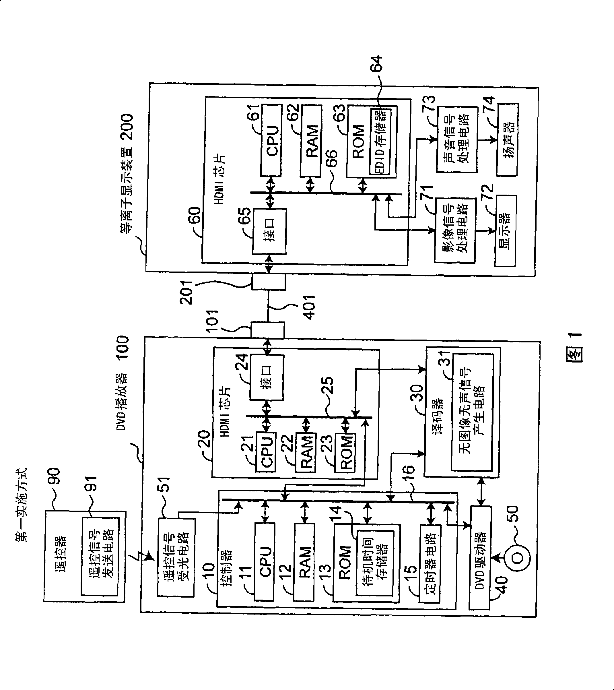
[0034] FIG. 1 is a block diagram showing the configuration of a DVD player 100 , a remote controller 90 and a plasma display device 200 according to the first embodiment of the present invention.

[0035] In Fig. 1, a DVD player 100 as an HDMI source device (a signal source device adopting the HDMI standard) communicates with a DVD player 100 as an HDMI sink device (a signal source device adopting the HDMI standard) through an HDMI connector 101, an HDMI cable 401, and an HDMI connector 201. The plasma display device 200 of the signal receiving device) is connected. Here, the HDMI cable 401 is a digital data transmission bus conforming to the HDMI specification, and the HDMI connectors 101 and 201 are data terminals conforming to the HDMI specification. In FIG. 1 , a DVD player 100 as an HDMI source device is characterized in that it includes a controller 10 that transmits video signals and audio signals to The plasma display device 200 outputs.

[0036] Further, the remote ...

no. 2 approach

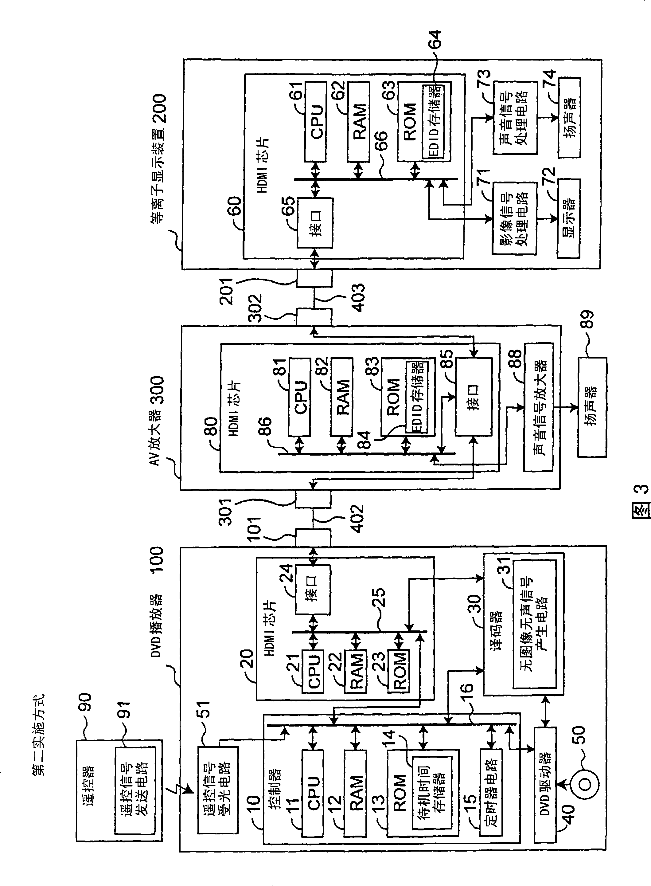
[0053] 3 is a block diagram showing the configuration of DVD player 100 , remote controller 90 , AV amplifier 300 , and plasma display device 200 according to a third embodiment of the present invention.

[0054] In Fig. 3, a DVD player 100 as an HDMI source device communicates with a signal receiving device (hereinafter referred to as HDMI repeater (repeater) device) The AV amplifier 300 is connected to the AV amplifier 300, and the AV amplifier 300 is connected to the plasma display device 200 as an HDMI receiving device through the HDMI connector 302, the HDMI cable 403 and the HDMI connector 201. Here, the HDMI cables 402 and 403 are digital data transmission buses conforming to the HDMI specification, and the HDMI connectors 301 and 302 are data terminals conforming to the HDMI specification. Compared with the first embodiment shown in FIG. 1 , this embodiment is characterized in that the CPU 11 of the DVD player 100 determines the standby time based on the data of the ma...


PUM


Abstract

The invention provides a DVD player (100) as a signal source device generating video signal and an audio signal and outputs them to a plasma display device (200) as a signal synchronization device. After equipment authentication between the DVD player (100) and the plasma display device (200) has been completed, the DVD player outputs video signal and an audio signal through transmission lines conforming to HDMI standards to the plasma display device (200) after a predetermined waiting time has elapsed, the waiting time being set to be longer than the time required for an initial startup setting process in the plasma display device (200).

Description

technical field [0001] The present invention relates to a signal source device that generates at least one of a video signal and an audio signal and outputs it to a signal sink device through a transmission path conforming to a prescribed standard, and a control method thereof. Background technique [0002] Conventionally, a source device such as a DVD player and a source device such as a DVD player have been proposed, which reproduce content to generate a digital video signal and a digital audio signal, and transmit the output to a video output device such as a liquid crystal display device or an audio output device such as a digital speaker. The control method thereof (for example, refer to Patent Documents 1 to 3, etc.). [0003] In recent years, high-quality multimedia has been proposed as an interface standard for transmitting digital video signals and digital audio signals from a source device such as a DVD player or a set top box to a receiving device such as a liquid...

Claims


Application Information

Patent Timeline
Patent Type & Authority Applications(China)
IPC IPC(8): H04N7/173G06F13/00G06F21/20G06F21/24G09G5/00G06F21/62H04N21/436
CPCG09G2330/026H04N2005/91364H04N21/4122G09G5/12G09G5/006H04N21/42646H04N5/85H04N5/775G09G2370/12G09G3/28
Inventor 米野润一
Owner PANASONIC CORP
Why Eureka
Try Eureka