Low stove pressure convection continuous roller bottom type annealing furnace and annealing technique

An annealing process and annealing furnace technology, which is applied in the field of low furnace pressure convection continuous roller hearth type bright annealing furnaces, can solve the problems such as the inability to meet the annealing requirements of ultra-long condenser tubes, the inability to completely eliminate the internal stress of the workpiece, and the short automation degree of the process. Achieve the effect of ensuring heat treatment quality, uniform and efficient heat transfer, and reducing airflow interference

Active Publication Date: 2008-08-27
SUZHOU ZHONGMENZI IND FURNACE TECH CO LTD
View PDF0 Cites 13 Cited by
  • Summary
  • Abstract
  • Description
  • Claims
  • Application Information

AI Technical Summary

Problems solved by technology

This process has the characteristics of short process, high degree of automation, and high yield. However, due to the continuous annealing process, the internal stress of the workpiece cannot be completely eliminated. Usually, after annealing, it is easy to break during the cold drawing process.
In addition, most of the traditional technical equipment is a periodic tank furnace or a continuous chain muffle furnace, which cannot meet the annealing requirements of the ultra-long condensation pipe (intermediate and finished pipe), which is also the technical problem that the present invention strives to overcome

Method used


Image

  • Low stove pressure convection continuous roller bottom type annealing furnace and annealing technique
  • Low stove pressure convection continuous roller bottom type annealing furnace and annealing technique
  • Low stove pressure convection continuous roller bottom type annealing furnace and annealing technique

Examples


Embodiment Construction

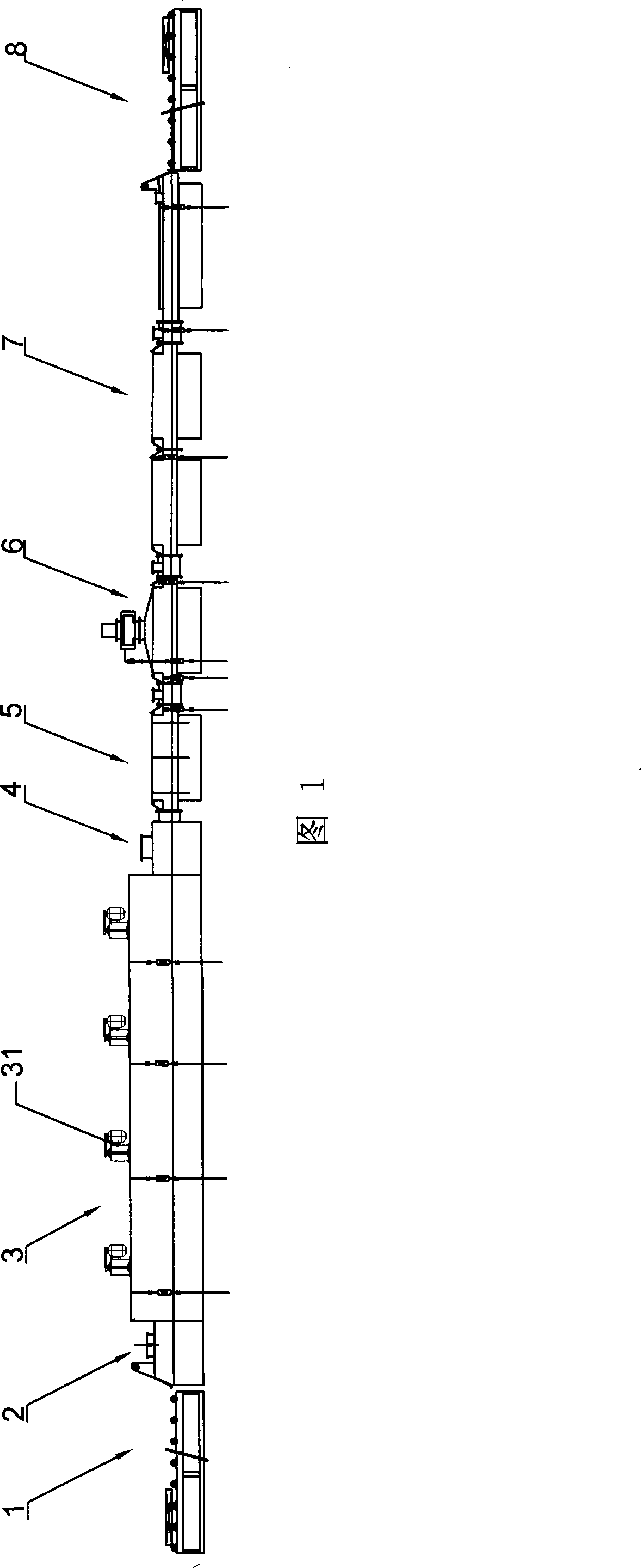
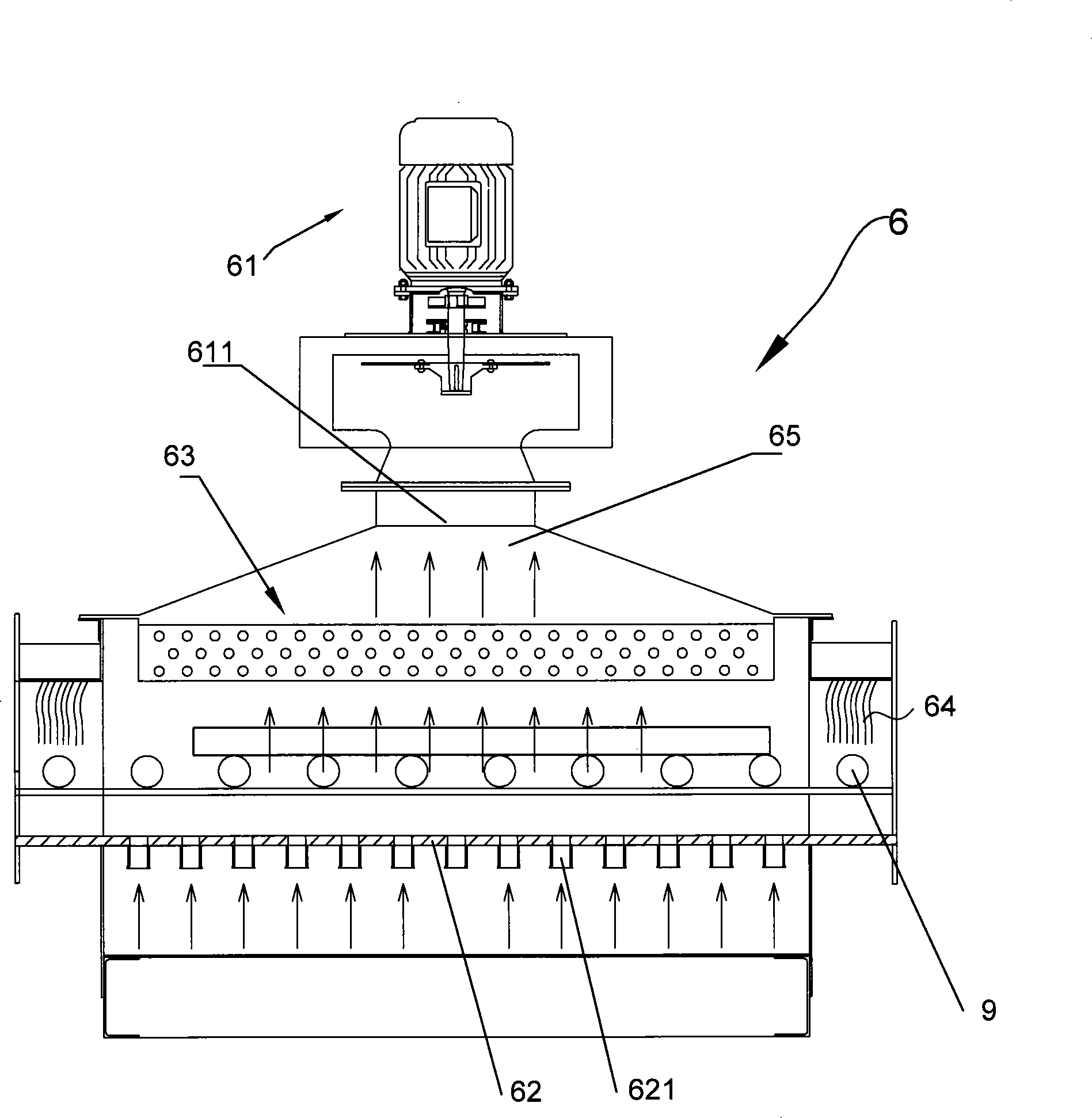
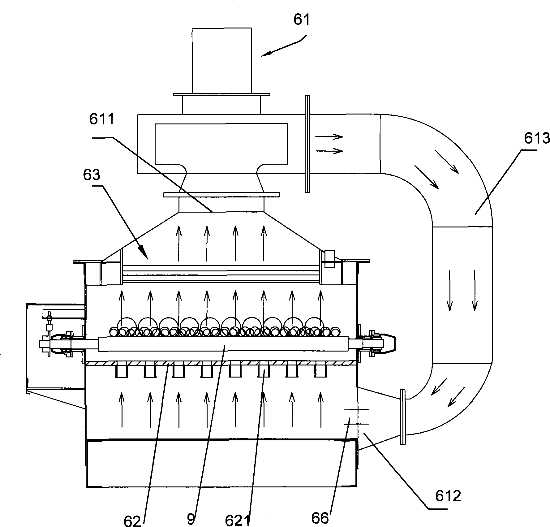
[0028] See attached drawings 1 to attached Figure 8 , a low furnace pressure convection continuous roller hearth annealing furnace, comprising a charging table 1, a front chamber 2, a heating chamber 3, a rear chamber 4, a water cooling chamber 5, a strong cooling chamber 6, a rear chamber 7, a discharge Platform 8 and the roller table transmission system running through the annealing furnace, the specific structure of each part is:

[0029] 1. Roller table transmission system: it is composed of a plurality of idler rollers 9 and gear sets, chains and motors connected with the plurality of idler rollers 9, and the plurality of idler rollers 9 move along the Continuous movement in the length direction of the roller, and a plurality of rollers 9 form a roller table that can continuously transport workpieces;

[0030] 2. Loading platform 1: It is mainly constructed by the skeleton of the material platform. The loading platform 1 is divided into two sections, which are automatic...


PUM


Abstract

The invention relates to a low furnace pressure convective continuous roller hearth type annealing furnace, which comprises a charging magazine, a heating chamber, a strong cooling chamber and a roller way driving system, wherein an internal circulation draught fan and a plurality of heating elements are arranged in the heating chamber, both an air inlet and an air outlet of the internal circulation draught fan are located in a furnace body of the heating chamber, the air inlet is vertical to the plane of a roller way, the air outlet is parallel to the plane of the roller way, an external circulation draught fan, a heat exchanger and a baffle plate are arranged in the strong cooling chamber, the baffle plate is located in the middle portion of the furnace body of the strong cooling chamber, the roller way is located between the heat exchanger and the baffle plate, an upper opening and a lower opening are respectively opened on the top and the bottom of the furnace body of the strong cooling chamber, the air inlet of the external circulation draught fan is communicated with the upper opening, the air outlet of the external circulation draught fan is connected with the lower opening through a connecting pipe which is arranged outside the strong cooling chamber, the complex number of nozzles are evenly distributed on the baffle plate, and the upper portion and the lower portion of the furnace body of the strong cooling chamber are communicated only through a complex number of nozzles. The annealing furnace of the invention has the advantages of even heating, rapid cooling, high efficiency and the like.

Description

technical field [0001] The invention belongs to the technical field of heat treatment of non-ferrous metals, and in particular relates to an annealing process suitable for copper and copper alloy intermediate pipes, and a low furnace pressure convection continuous roller hearth bright annealing furnace. Background technique [0002] In recent years, with the rapid development of China's economy, China's non-ferrous metal copper processing industry has continued to grow, and its production volume has continued to expand. Among them, the processing and production of condensation pipes has become one of the leading products of major domestic copper processing enterprises. Condensation pipes are thermal power, An important material for heat exchange condensers in ships, seawater desalination, sugar, salt, chemical, nuclear power, etc. The reliability of the condensing tube directly affects the safe and economical operation of the entire generator set. Therefore, the processing a...

Claims


Application Information

Patent Timeline
Patent Type & Authority Applications(China)
IPC IPC(8): C22F1/08
Inventor 蒋明根
Owner SUZHOU ZHONGMENZI IND FURNACE TECH CO LTD
Why Eureka
Try Eureka