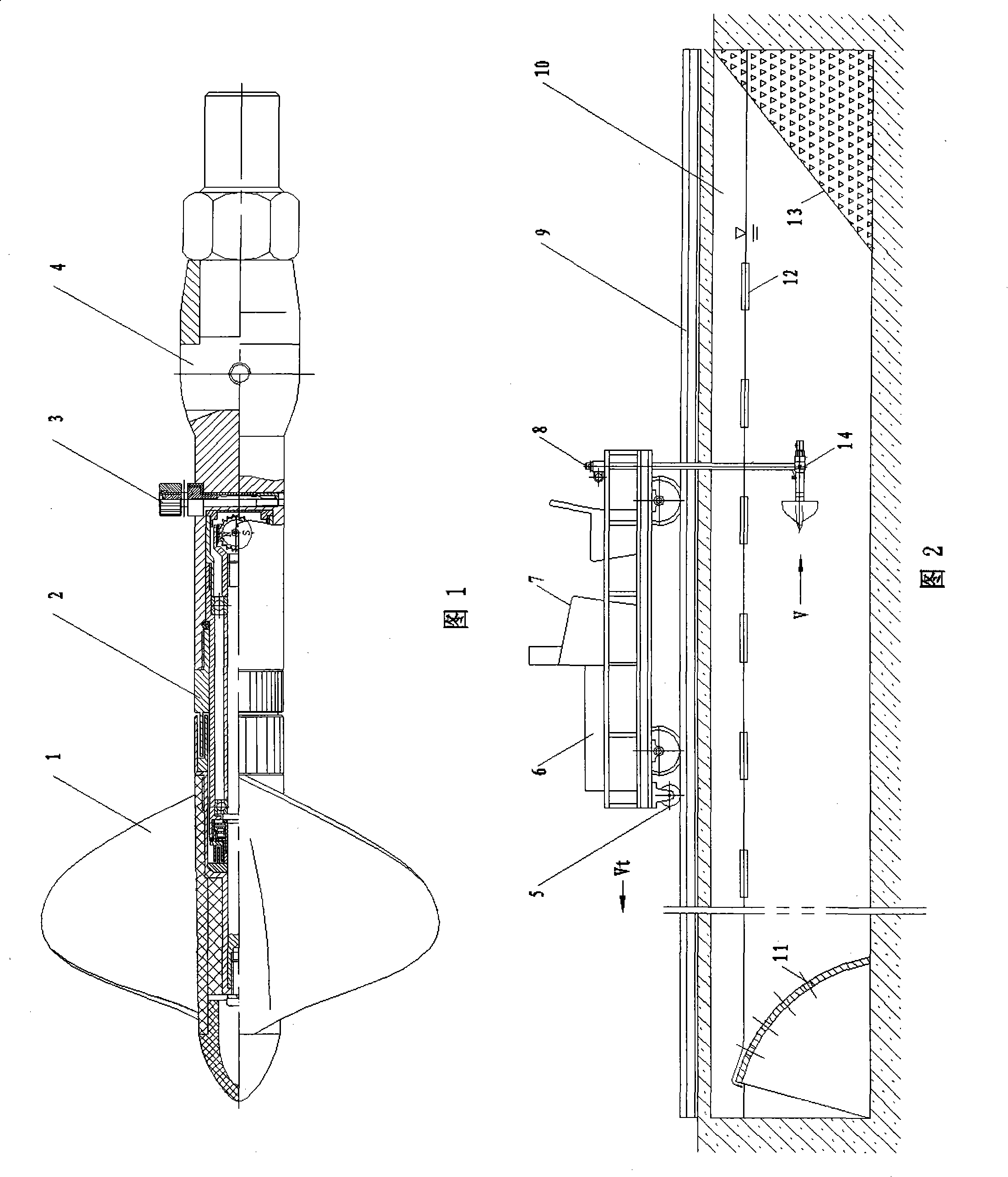
Method for designing rotary oar current meter norm edit value slow speed straight line formula

A design method and technology of flow meter, applied in speed/acceleration/shock measurement, testing/calibration of speed/acceleration/shock measurement equipment, instruments, etc., can solve problems such as complicated procedures, power consumption, and fuel consumption

Inactive Publication Date: 2008-08-27
JIANGSU NANSHUI TECH
View PDF2 Cites 13 Cited by
  • Summary
  • Abstract
  • Description
  • Claims
  • Application Information

AI Technical Summary

Problems solved by technology

[0024] (2) Still water time: lack of clear technical indicators and corresponding detection methods
If the requirements are not met, the instrument needs to be disassembled, adjusted, cleaned, refueled, installed, and re-verified. The process is complicated and labor-intensive
[0026] (4) Verification man-hours: the speed measurement range of the low-speed part only accounts for 2% of the total range, but the verification time accounts for half of it, which takes a lot of time
[0028] (6) Verification operation: The verification workflow is long, labor-intensive, time-consuming, labor-intensive, electricity-intensive, and oil-intensive, including high-grade gasoline and instrument oil for cleaning instruments. There are many staff, complex equipment, and a large area. Investment and operation management high cost, low benefit
[0029] (7) Data processing: production and use of low-speed V 1 ~n 1 Drawings of relationship curves are labor-intensive and time-consuming, especially for flow measurement in the harsh working environment in the field. They are easy to be damaged after long-term use, inconvenient to read, and difficult to digitize.
At present, for the low-speed part, people still use the low-speed curve to read, the accuracy is poor, and it is inconvenient

Method used


Image

  • Method for designing rotary oar current meter norm edit value slow speed straight line formula
  • Method for designing rotary oar current meter norm edit value slow speed straight line formula
  • Method for designing rotary oar current meter norm edit value slow speed straight line formula

Examples


Embodiment Construction

[0126] The present invention will be described in detail below in conjunction with the accompanying drawings.

[0127] 1 Introduction

[0128] (1) Waveform analysis of flow meter verification signal

[0129] Figures 3a-3e Shown is the low-speed verification signal waveform diagram of the propeller current meter in the water tank. Total V 0 , V 1 ......V K 5 speed levels, each speed level includes time signal T, distance signal L and propeller low-speed rotation number N 1Waiting for 3 parameters, the thick solid line is a positive pulse waveform, according to which, it can be calculated: Verification car speed V t =L / T; propeller speed n=N 1 / T. The ideal rotation number N of the propeller is the negative pulse of the thin solid line, which means that there is no slippage during the operation of the propeller. N 1 The difference Q from the N signal distance is the slippage during the propeller operation. Figure 3a middle: n 1-0 = 0.135 rev / s, n 0 = 0.167 rev / s, V...


PUM


Abstract

The invention relates to a design method for a low speed straight-line formula of a standard revision value of a helical current meter; the invention is characterized in that the steps of the method are as follows: the method is based on a high speed straight-line formula V=Kn+C, and uses a cut line to replace a low speed curve line; the cut line formula is as follows: V1=K1n1+C1; the inflection point formula is as follows: Vk=KnK+C; C1=C+delta C and delta K=delta C / nK are inputted in the low speed straight-line formula, and V1=(K-delta K)n1+(C+deltaC) is obtained; equalizing values which are calculated according to the high and the low straight-line formulas are as follows: delta K=0.0122 and delta C =0.0081, which are inputted in V1=(K-delta K)n1+(C+delta C) to obtain V1=(K-0.0122 )n1+(C+0.0081). The invention does not need to be tested under water while being manufactured; only if the initial rotation speed test meets the standard, the high speed straight-line formula is revised to the low speed straight-line formula by the standard revision value; when the invention is used by a user, directly reading the current velocity can be realized, thereby the method is quite convenient and has good technical, economic and social benefits.

Description

technical field [0001] The invention relates to a processing method and expression for low-speed performance verification data of a propeller current meter, in particular to a design method of a low-speed straight line formula of a propeller current meter, belonging to the field of river hydrological testing. Background technique [0002] The current meter is a routine instrument for river hydrological testing. In order to ensure the accuracy of the instrument measurement, it is necessary to test and verify the performance of the current meter before use. At present, the low-speed performance testing equipment and methods of the propeller current meter, all countries have formulated their national current meter verification standards according to the guiding principles stipulated in the international standard ISO3455 "Verification of Rotor-type Flow Meters in Straight-line Open Channels". The structure and performance are manufactured, tested and verified according to the st...

Claims


Application Information

Patent Timeline
Patent Type & Authority Applications(China)
IPC IPC(8): G01P21/02
Inventor 杨汉塘
Owner JIANGSU NANSHUI TECH
Why Eureka
Try Eureka