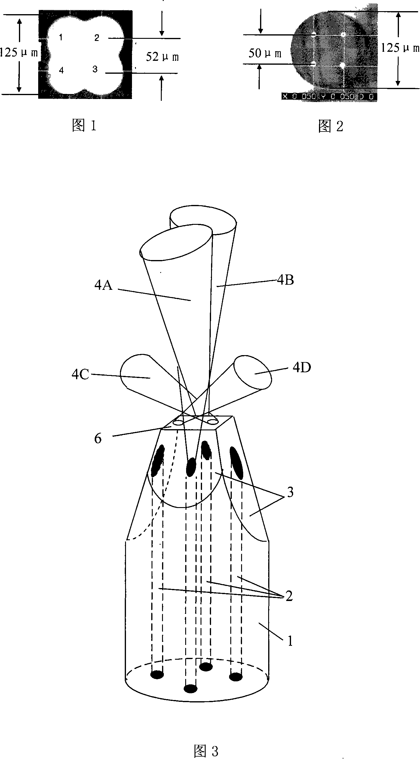
Multiple light forceps integrated on simple optical fiber
A single-fiber, optical tweezers technology, applied in the field of optical tweezers, can solve the problem that the capture force of the single-fiber optical tweezers cannot be further increased, and achieve the effects of improving the capture characteristics, low price, and increasing the cross angle.
- Summary
- Abstract
- Description
- Claims
- Application Information
AI Technical Summary
Problems solved by technology
Method used
Image
Examples
Embodiment 1
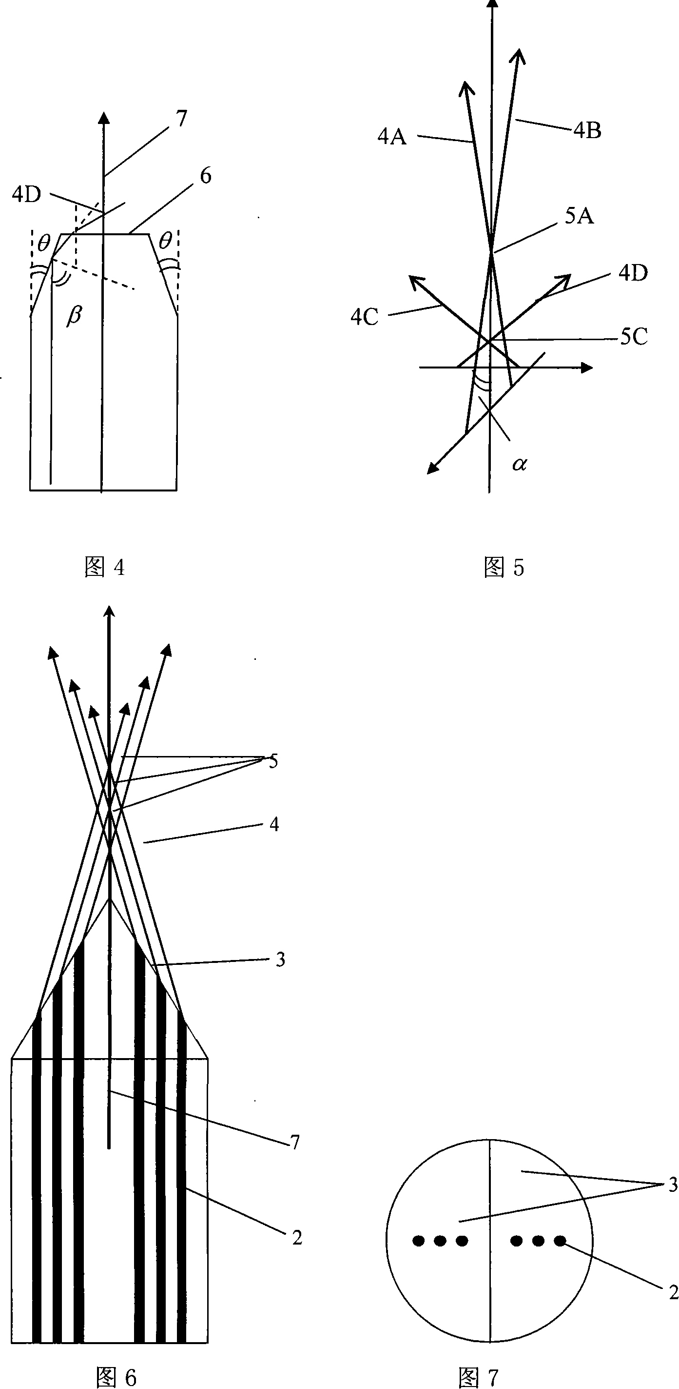
[0043] The following describes the implementation of the combination and integration of axially symmetrical wedge-shaped multi-fiber optical tweezers based on the principle of beam refraction, as shown in FIG. 6 and FIG. 7 . The method of combining and integrating the multi-fiber optical tweezers is realized by using the six-core optical fiber with axisymmetric linear geometric distribution and grinding the end faces thereof. The wedge-shaped grinding processing method of the six-core optical fiber is as follows:
[0044] (1) Select a six-core optical fiber with the above structure, remove the coating layer, clean it with a mixture of alcohol and ether, and set it aside;
[0045] (2) Put a certain size of polishing sandpaper on the polishing disc on the optical fiber end grinder, fix the cleaned six-core optical fiber, and place one end on the grinding disc;
[0046] (3) Rotate the optical fiber so that the fiber core line is in a plane perpendicular to the grinding disc, and...
Embodiment 2
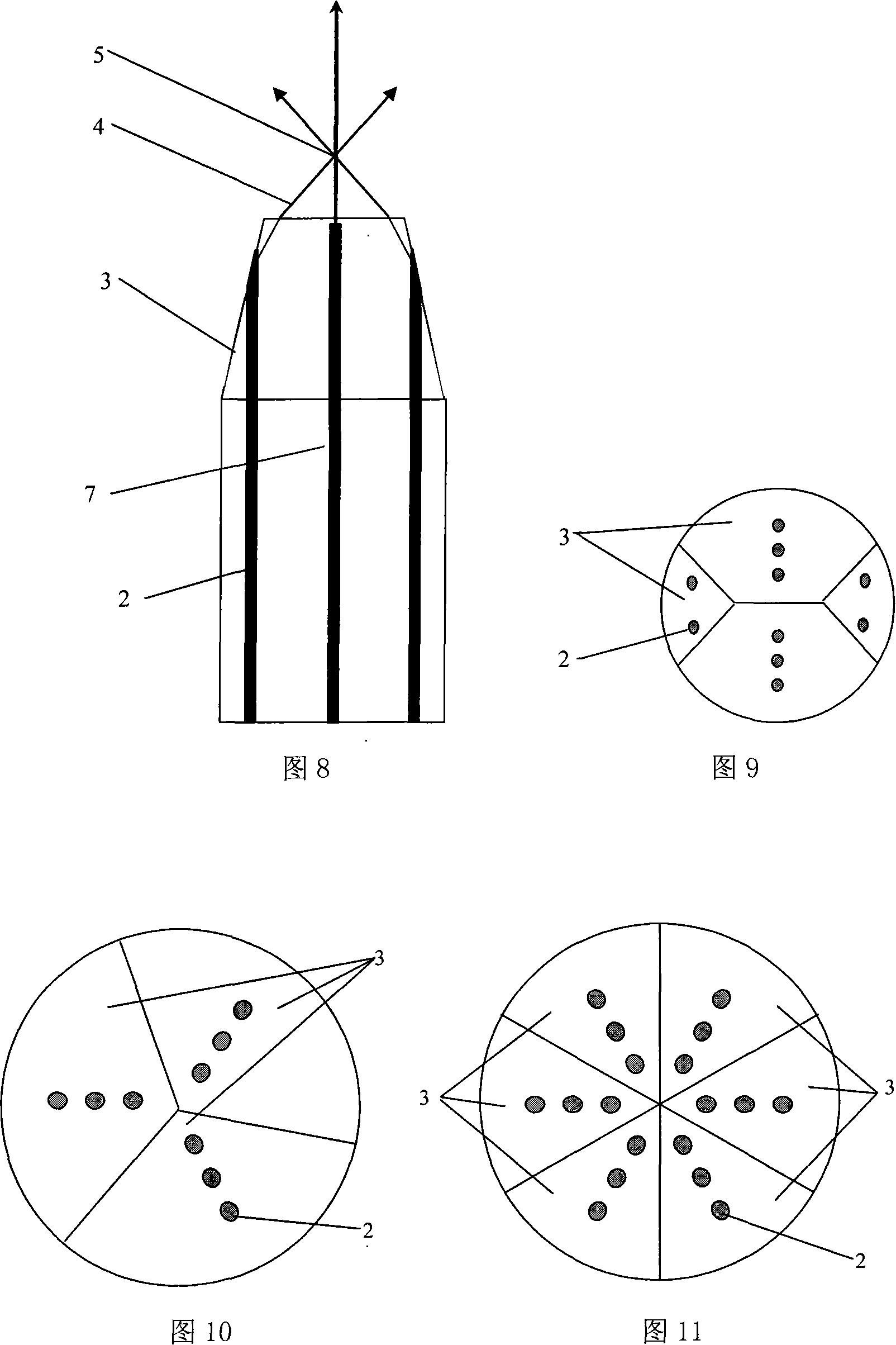
[0052] The following describes the implementation of the combination and integration of axially symmetrical quadrangular pyramidal multi-fiber optical tweezers based on the principle of total reflection-refraction, as shown in Figure 8 and Figure 9 . The structure of the multi-core optical fiber is based on the six-core optical fiber with linear geometric distribution, and two cores are added in the vertical direction to form a 10-core optical fiber. The combination and integration of multi-fiber optical tweezers can be realized by grinding and processing them. The grinding process of the quadrangular cone of the 10-core optical fiber is as follows:
[0053] Wherein steps (1) to (4) are identical with the grinding process of wedge-shaped end;
[0054] (5) After one side of the optical fiber is polished, the optical fiber is rotated 90° along the axis. At this time, the size of the grinding angle θ can be reset through the program to realize the grinding and polishing of the o...
Embodiment 3
[0058] The combination and integration of multi-fiber optical tweezers can also be realized by using 9-core optical fibers distributed axially symmetrically, as shown in Figure 10. The implementation method and process are similar to those in Example 1, except that it is necessary to grind and process an axially symmetrical triangular cone fiber end structure according to the geometric distribution symmetry of the core in the optical fiber. The three lateral grinding angles of the optical fiber need to be the same, but you can choose a complementary angle larger than the critical angle of total reflection to achieve direct refraction focusing, or you can choose a complementary angle smaller than the critical angle of total reflection to achieve total reflection-refractive focusing.
PUM
 Abstract
Description
Claims
Application Information
 - R&D
- Intellectual Property
- Life Sciences
- Materials
- Tech Scout
- Unparalleled Data Quality
- Higher Quality Content
- 60% Fewer Hallucinations
Browse by: Latest US Patents, China's latest patents, Technical Efficacy Thesaurus, Application Domain, Technology Topic, Popular Technical Reports.
© 2025 PatSnap. All rights reserved.Legal|Privacy policy|Modern Slavery Act Transparency Statement|Sitemap|About US| Contact US: help@patsnap.com


