Eureka AIR delivers breakthrough ideas for toughest innovation challenges, trusted by R&D personnel around the world.

Vibrating-type motor

A motor and vibration technology, applied in the direction of electrical components, electromechanical devices, etc., can solve the problems that the piston and the cylinder cannot be supported in a non-contact manner, and the structure is heavy, and achieve the effect of light weight, low price and small size

Inactive Publication Date: 2008-08-27
FUJI ELECTRIC CO LTD
View PDF3 Cites 4 Cited by
  • Summary
  • Abstract
  • Description
  • Claims
  • Application Information

AI Technical Summary

Problems solved by technology

However, these countermeasures still have problems: the piston and cylinder cannot be supported in a non-contact manner, and the whole structure is heavy and bulky

Method used


Image

  • Vibrating-type motor
  • Vibrating-type motor
  • Vibrating-type motor

Examples


Embodiment Construction

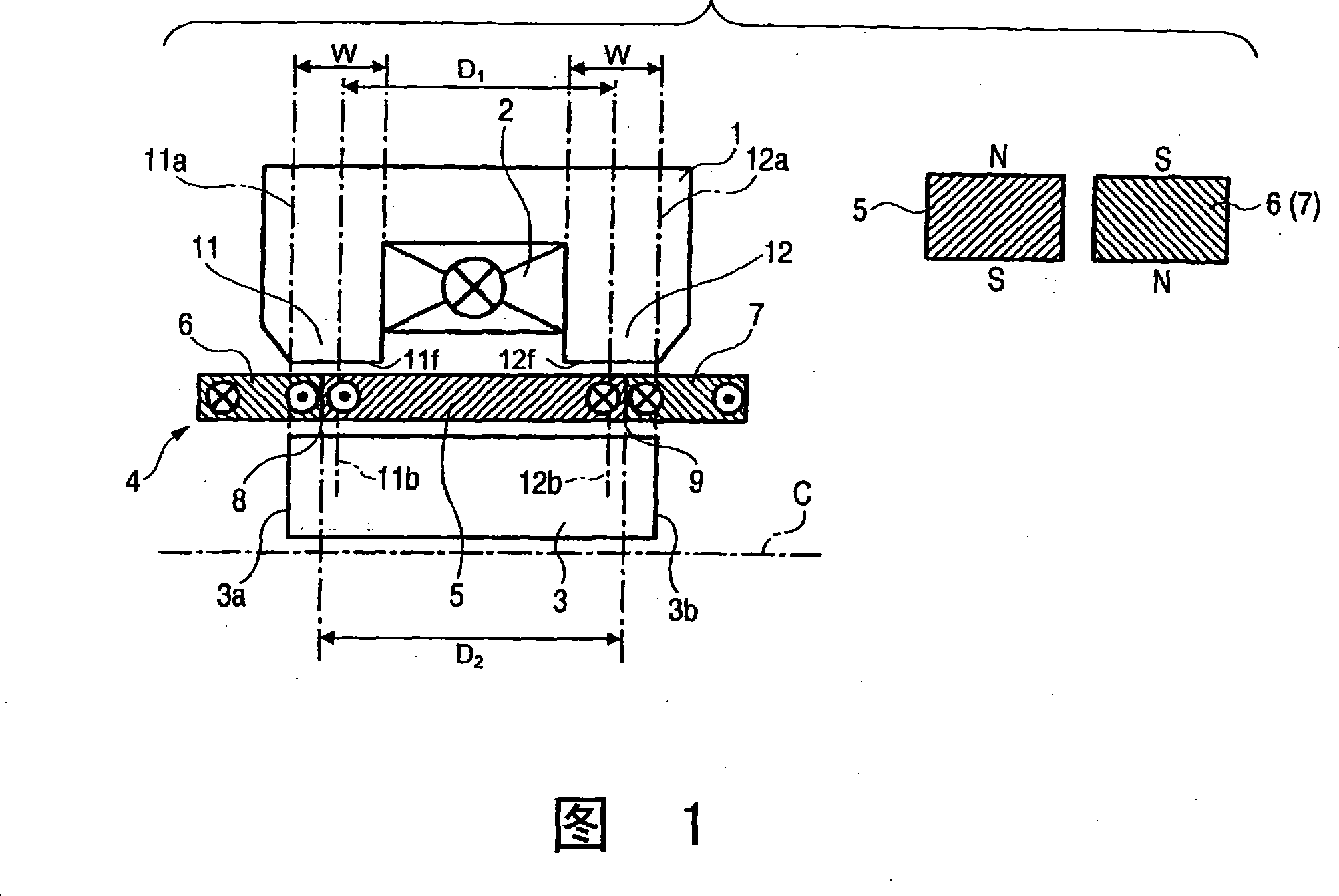
[0037] FIG. 1 is a schematic diagram showing a vibration motor according to the present invention. As discussed above with regard to FIGS. 6 to 9 , FIG. 1 shows a portion of a section taken along the central axis C of a substantially cylindrical motor. FIG. 1 shows a motor, which includes a field yoke 1 , a field coil 2 wound on the field yoke 1 , a back yoke 3 and a moving part 4 . The moving part 4 is formed by a permanent magnet arranged in a yoke gap portion between the field yoke 1 and the back yoke 3 . A conventional frame for supporting the moving part 4 is not shown in the figures.

[0038] As shown in FIG. 1, the moving part 4 is constructed by coaxially and integrally connecting the auxiliary magnets 6 and 7 at connection positions 8, 9 to the two-axis ends of the main magnet 5, wherein the main magnet 5 has its outer circumferential side as N pole and its inner circumference side is S pole. The auxiliary magnets 6 and 7 are magnetized in the opposite direction to...


PUM


Abstract

A vibrating-type motor is provided, in which a restoring force is reduced without reducing a thrust increasing effect by auxiliary magnets, thereby to reduce the size and expense of the motor while increasing efficiency. The vibrating-type motor includes a moving part having a main magnet and auxiliary magnets individually junctioned coaxially to two axial end portions of the main magnet, an exciting yoke including two leg portions opposed to the moving part through a gap and arranged coaxially with the moving part, an exciting coil wound on the exciting yoke for generating a magnetic flux in the leg portions, and a back yoke arranged to confront the exciting yoke with the moving part located between the back yoke and the exciting yoke, wherein outer-side end portions of the exciting yoke extend past axial end portions of the back yoke.

Description

technical field [0001] The present invention relates to vibratory motors which may be used in vibratory compressors such as Stirling refrigerators. Background technique [0002] A moving magnet linear motor (hereinafter simply referred to as a "moving magnet motor") is generally used as a vibration motor. 4 and 5 are schematic diagrams explaining the driving principle of the moving magnet motor, and show part of a cross-section taken along the central axis C of the substantially cylindrical motor. As shown in FIG. 4 , the motor includes an excitation yoke 101 , an excitation coil 102 , a back yoke 103 and a moving part 104 . The moving part 104 is made of a cylindrical permanent magnet arranged in a gap portion between the field yoke 101 and the back yoke 103 and differs in magnetic poles on the inner and outer circumferential sides. Also shown is the magnetic flux 201 generated by the moving part 104 . A conventional housing for supporting the moving part 104 is provided...

Claims


Application Information

Patent Timeline
IPC IPC(8): H02K33/18
Inventor 松本伸大岛惠司沟口义则
Owner FUJI ELECTRIC CO LTD
Why Eureka
Eureka Blog
Learn More