Vacuum turbomolecular pump

A turbomolecular pump and vacuum technology, applied in pumps, pump control, axial flow pumps, etc., can solve problems such as increased costs

Active Publication Date: 2008-08-27
LEYBOLD HERAEUS GMBH & CO KG
View PDF0 Cites 5 Cited by
  • Summary
  • Abstract
  • Description
  • Claims
  • Application Information

AI Technical Summary

Problems solved by technology

[0005] The current safety requirements therefore require a separate second rotational frequency control device, which together with additional sensors, additional time base circuits, etc. adds significantly to the additional cost

Method used


Image

  • Vacuum turbomolecular pump

Examples


Embodiment Construction

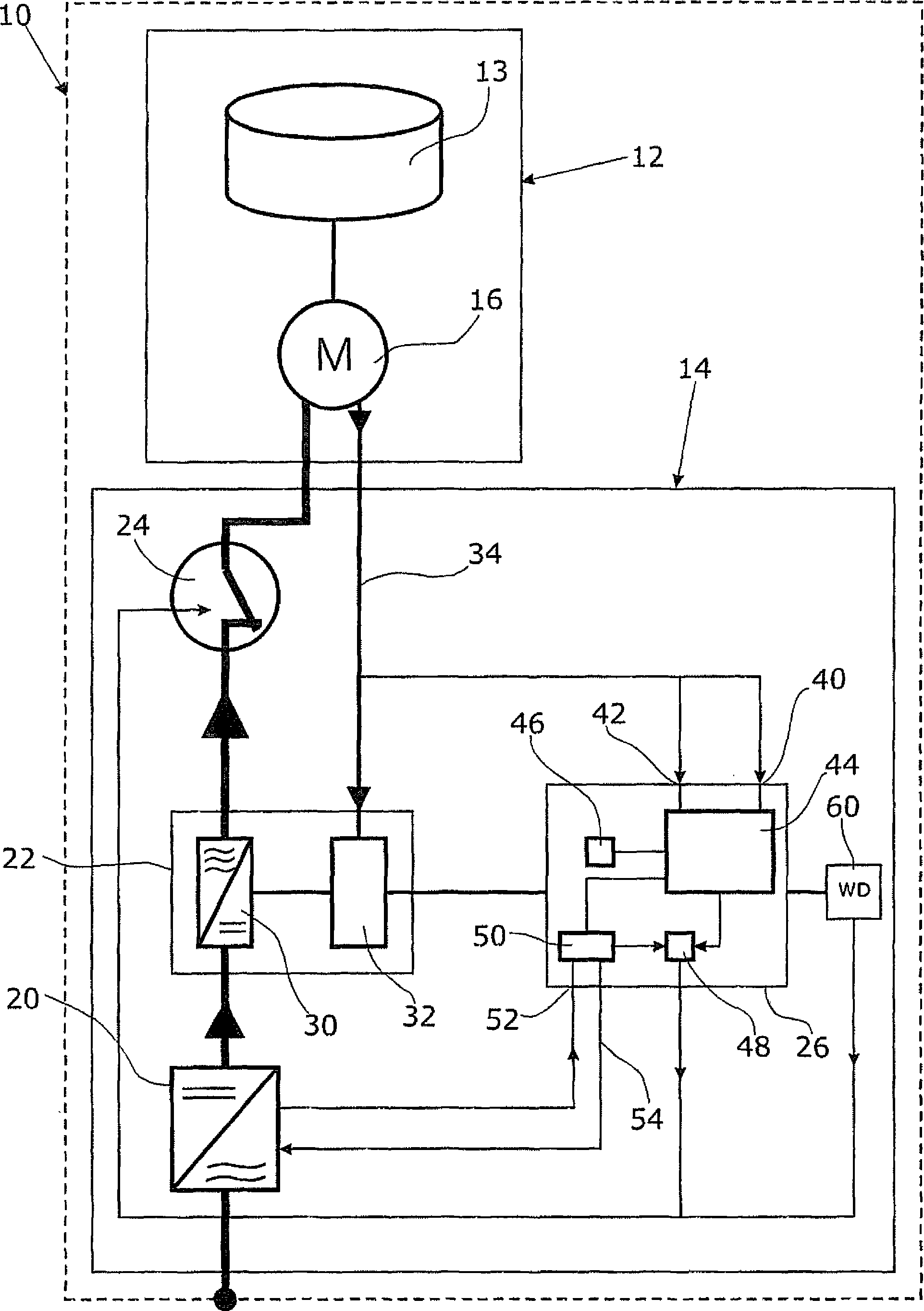
[0025] The drawing shows a high-speed rotating vacuum turbomolecular pump 10 which basically comprises a pump unit 12 and a control unit 14 . Turbomolecular pumps are used to generate high vacuum. This turbomolecular pump operates at a nominal rotational frequency f of 300 to 1600 Hz N run. The pump unit 12 has a pump rotor 13 and a drive motor 16 .

[0026] The control unit 14 includes the following main components: a power supply 20 , a motor control device 22 , a disconnection module 24 and a protection device 26 . The control unit 14 is used to control and monitor the drive motor 16 .

[0027] Due to the high rated rotational frequency of vacuum turbomolecular pumps, the rated rotational frequency f designed for the strength of the pump rotor should not be significantly exceeded N . Otherwise, the centrifugal force would be so high that the pump rotor 13 , or rather the rotor blades, would be damaged and could be thrown off dangerously. Since the casing of the pump u...


PUM


Abstract

A vacuum turbomolecular pump (10) is driven by a brushless direct current drive motor (16), which has stator coils and a permanent magnetic-exited motor rotor. When rotating, the motor rotor produces an electromotive force oriented counter to the direction of rotation. A motor controller (22) is provided, which is connected to the stator coils and which generates a current from the supply voltage, this current being impressed into the stator coils. In addition, a rotary frequency regulator (32) is provided that limits the rotary frequency (f) of the drive motor (16) to a nominal rotary frequency (fN). A power supply (20) is provided, which is connected to the motor controller (22) and which supplies a constant direct current voltage as a supply voltage for the motor controller (22).; The power supply (20) is designed so that the constant supply voltage (UV) is low enough that at a limit rotary frequency (fG), the electromotive force is equal to the drive force that can be maximally generated by the motor controller (22) and by the stator coils. The limit rotary frequency (fG) is less than 1.3 times the nominal rotary frequency (fN). As a result, the motor output is limited and the rotary frequency of the drive motor (16) is physically restricted to a limit rotary frequency (fG) in a reliable manner.

Description

technical field [0001] The invention relates to a vacuum turbomolecular pump with a DC drive motor with a permanent magnet motor rotor and stator coils. Background technique [0002] Vacuum turbomolecular pumps are high-speed rotating turbines with a maximum rotational speed of 20,000 to 100,000 revolutions per minute or a maximum rotational frequency in the range of 300 Hz to 1700 Hz. Brushless DC drive motors comprising permanent magnet motor rotors are often used as drives for pump rotors due to their favorable loss power balance. [0003] At high rotational frequencies, rotor parts that are detached from the rotor during operation have very high kinetic energy. In the event of a collision, vacuum turbomolecular pumps which rotate at a high rotational frequency already present a high risk of injury to persons. This risk can only be reduced by a corresponding retrofitting of the pump stator, but this requires considerable outlay. Especially in the case of large turbines...

Claims


Application Information

Patent Timeline
Patent Type & Authority Applications(China)
IPC IPC(8): F04D19/04F04D27/02H02P6/16H02P6/18
CPCF04D27/008F04D19/04F04D27/0261F04D27/0292Y02B30/70
Inventor 阿洛伊斯·格雷文克里斯蒂安·哈里希
Owner LEYBOLD HERAEUS GMBH & CO KG
Why Eureka
Try Eureka