
LED light source for backlighting with integrated electronics

A light-emitting diode and backlight technology, applied in the field of white light backlight, can solve the problems that printed circuit boards cannot be completely suppressed, expensive, and time-consuming

Active Publication Date: 2008-08-27
SIGNIFY NORTH AMERICA CORP
View PDF0 Cites 33 Cited by
  • Summary
  • Abstract
  • Description
  • Claims
  • Application Information

AI Technical Summary

Problems solved by technology

This process of using binning patterns and grading in order to produce a board with uniform light characteristics and achieve a target white point is expensive and time consuming
In addition, variations within the PCB cannot be fully suppressed

Method used


Image

  • LED light source for backlighting with integrated electronics
  • LED light source for backlighting with integrated electronics
  • LED light source for backlighting with integrated electronics

Examples


Embodiment Construction

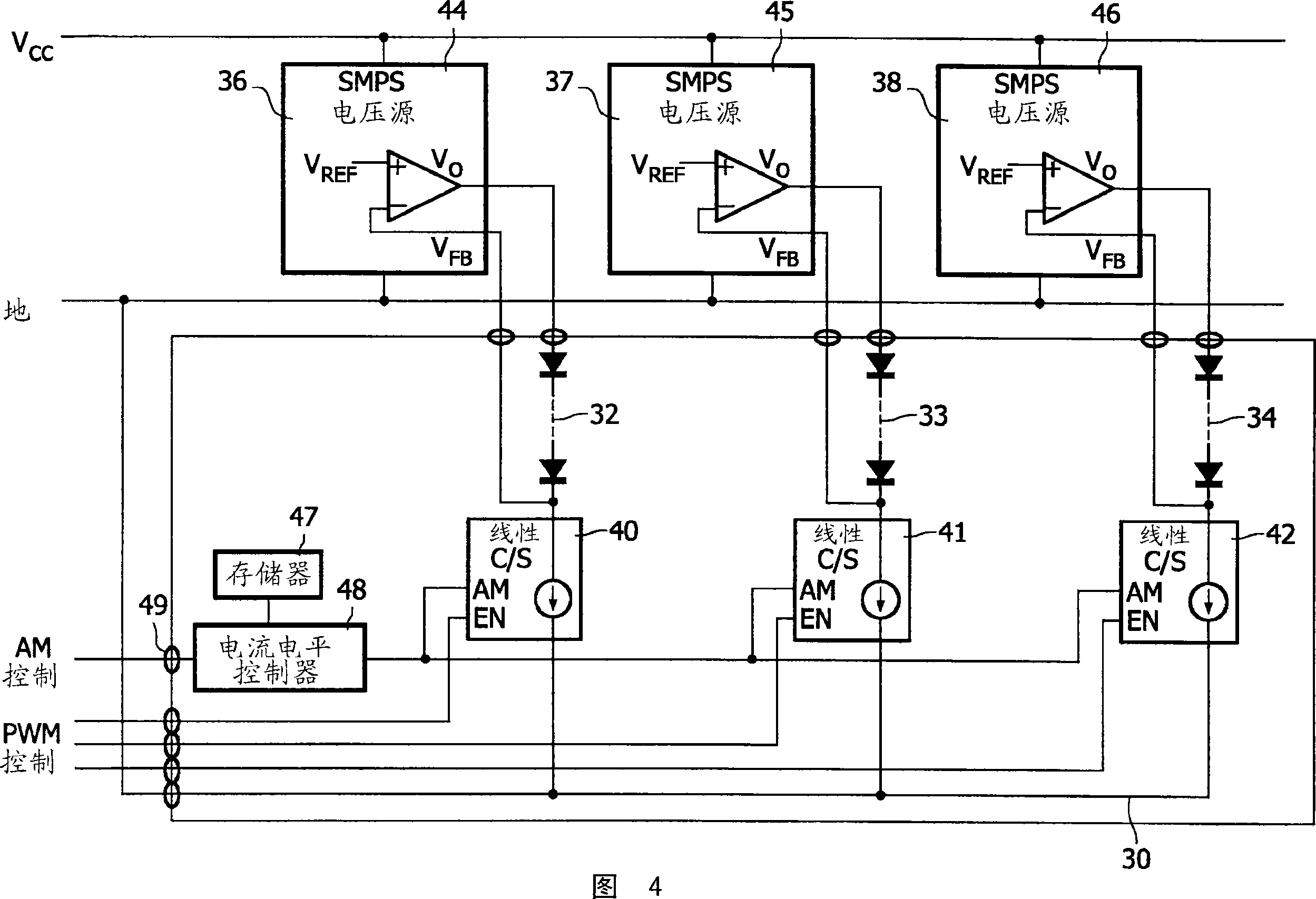
[0035] Figure 4 shows the electronics and light sources of a backlight printed circuit board for a liquid crystal display. In one embodiment, the light emitting diodes and current source are mounted on a single printed circuit board (PCB) 30 . In another embodiment, the voltage regulator is also mounted on the printed circuit board 30 .

[0036]A series string of red LEDs 32 , green LEDs 33 and blue LEDs 34 is shown. By adjusting the current through the red, green and blue LEDs, any white point can be achieved by the backlight.

[0037] The anode of each string is connected to its own voltage regulator 36,37,38 and the cathode of each string is connected to its own current source 40,41,42.

[0038] The voltage regulator is preferably a switching regulator, sometimes called a switch mode power supply (SMPS). Switching regulators are very efficient. One suitable type is a conventional pulse width modulated (PWM) regulator. The regulators are represented as differential ampl...


PUM


Abstract

An LED backlight structure and technique for setting the voltages and currents for the LEDs are described. In one embodiment, red LEDs are connected in series between a first voltage regulator and a first controllable current source, green LEDs are connected in series between a second voltage regulator and a second controllable current source, and blue LEDs are connected in series between a third voltage regulator and a third controllable current source. The current sources may linear current regulators. After all the LEDs are mounted on a printed circuit board, each voltage regulator is controlled so that there is a minimum voltage drop across the current source to minimize energy dissipation by the current source. Also, after all the LEDs are mounted on the printed circuit board, the current sources are controlled to balance the three colors to achieve a target light output of the board using a light detection chamber. In another embodiment, a constant current source is connected to the series string of LEDs. PWM controllers control transistor switches connected in parallel across groups of LEDs, where the duty cycles set the average current through each group of LEDs. The control values used to achieve the target light characteristics are then stored in a memory on the board. With such a technique, LEDs do not need to be binned to match their efficiencies, since the controllable voltage and current sources compensate for the variety of LED efficiencies. Accordingly, all boards will have the same target light output using the particular values stored on each board. In other embodiments, not all the LEDs of a particular color are connected in series. The brightness levels of the LEDs may be further controlled by a PWM controller. The backlight may be for an LCD television or other color display.

Description

technical field [0001] The present invention relates to the control of light emitting diodes (LEDs) to produce white light backlights, eg for liquid crystal displays (LCDs). Background technique [0002] LCD displays require a backlight. For full-color LCDs, the backlight is a white light source. The white point of the white light source is generally set by the manufacturer of the liquid crystal display, and for different applications, the white point may be different. The white point is specified by temperature. One application for liquid crystal displays is as a television or computer monitor. [0003] Common white backlights are produced either by fluorescent bulbs or a combination of red, green, and blue light-emitting diodes. [0004] For medium and large backlights, multiple LEDs of each color are used. On a printed circuit board (PCB), all LEDs of one color are usually connected in series. In general, external current drivers are used in the backlight, each driv...

Claims


Application Information

Patent Timeline
IPC IPC(8): H05B33/08H05B44/00
CPCY10S362/80Y02B20/347H05B33/0827H05B33/0821H05K1/181H05B33/083H05B33/0815G02F1/133603G02F1/133609H05B45/40H05B45/48H05B45/46Y02B20/30H05B45/3725
Inventor P·格鲁特斯N·凯托R·F·M·亨德里克斯C·A·施拉马E·N·H·J·斯塔萨D·克莱森斯
Owner SIGNIFY NORTH AMERICA CORP
Learn More