Voltage-compensating water supply installation and method without additional infection of common ductwork hydraulic pressure

A water supply device and pipe network technology, which is applied in the direction of water supply devices, water supply main pipelines, water supply pipeline systems, etc., can solve the problems that are difficult to be fully promoted, not conducive to energy saving, environmental protection, and the difficulty of increasing the installation of surge tanks and antifreeze.

Inactive Publication Date: 2008-09-03
张新群
View PDF3 Cites 0 Cited by
  • Summary
  • Abstract
  • Description
  • Claims
  • Application Information

AI Technical Summary

Problems solved by technology

This is a common concern, and it is also an important reason why it is difficult to fully promote the technology
In addition, just to prevent negative pressure, the water head of 20 meters and 30 meters in the municipal pipe network cannot be fully utilized; the power of the pressurization equipment must be increased; it also increases the difficulty of installing and antifreezing the surge tank, which is not conducive to energy saving and environmental protection

Method used


Image

  • Voltage-compensating water supply installation and method without additional infection of common ductwork hydraulic pressure
  • Voltage-compensating water supply installation and method without additional infection of common ductwork hydraulic pressure
  • Voltage-compensating water supply installation and method without additional infection of common ductwork hydraulic pressure

Examples


Embodiment Construction

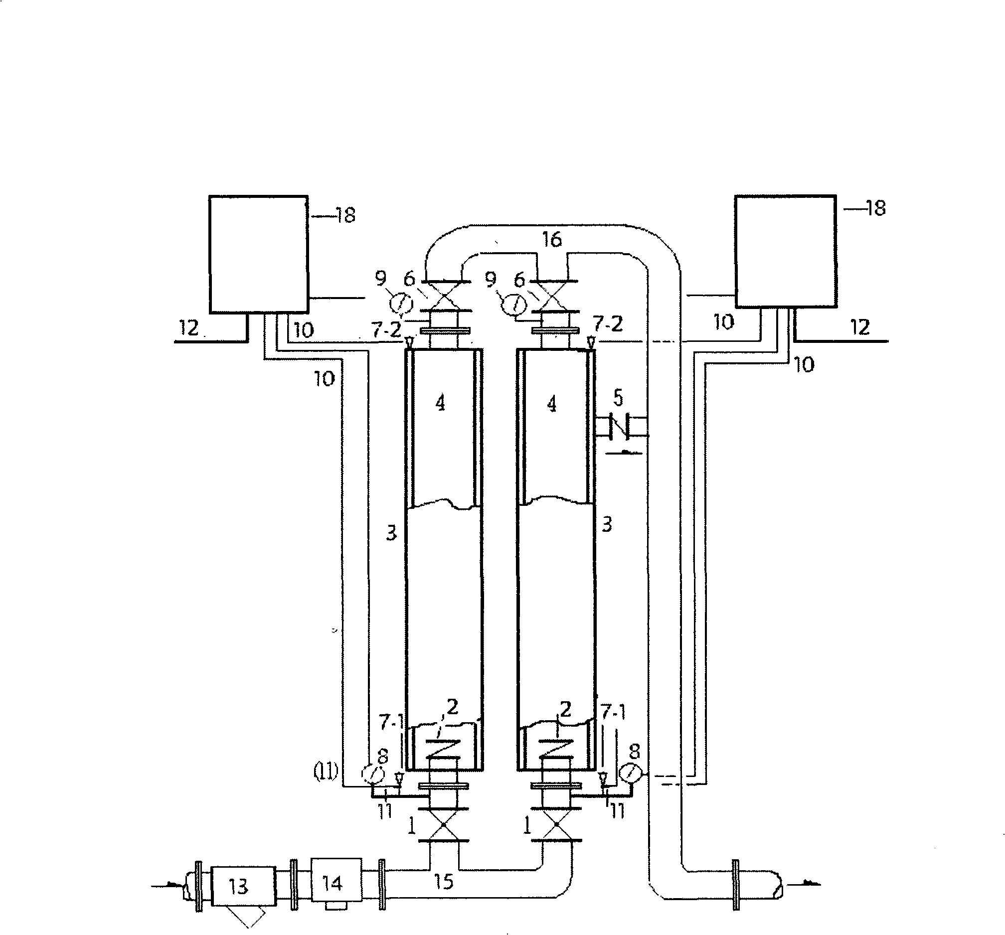
[0040] figure 1 , is a structural schematic diagram of the pressure supplement water supply device of the present invention (both expressed by vertical installation). in the figure 1 In the above, the content represented by the marks used is: 1-water inlet valve, 2-one-way valve, 3-equipment body, 4-motor water pump, 5-bypass one-way valve, 6-water outlet valve, 7-1-the first One breather valve, 7-2-second breather valve, 8-limited low pressure gauge, 9-outlet water pressure sensor, 10-signal cable, 11-water shortage protection device, 12-power cable, 13-water filter valve, 14- Anti-backflow device, 15-water inlet pipe, 16-water outlet pipe, 17-municipal utility pipe, 18-control device. The same symbols in the figures represent the same contents.

[0041] Such as figure 1 As shown, the described pressurized water supply device includes:

[0042] At least one device body (3), the device body (3) includes a motor water pump (4) and a one-way valve (2), the device body (3...


PUM


Abstract

The present invention discloses a pressure-compensating water-supplying device which does not additionally affect the hydraulic pressure of the common ductwork. The device comprises the following components: at least one equipment body, a water inlet valve, a water outlet valve, a bypass one-way valve, a first and a second ventilation valves, a low pressure restraining instrument (8), a water shortage protective device, a water discharging pressure sensor and at least one control device. The method comprises the steps of detecting the pressures of the water inlet valve and the water outlet valve by the control device through the low pressure restraining instrument and the like for generating the data information of the water pressure of the water inlet valve and the water outlet valve and the like, and transmitting the information to the control device through the signal cable for controlling. The device uses a totally sealed electric underwater pump to directly take water from the common ductwork for pressurization without the water pool, the water tank or the voltage stabilization of the voltage stabilization pot. The invention has the advantages of realizing voltage-stabilizing water supply without additionally reducing the pressure of the common ductwork, no pollution to the water quality, automatic running, more energy-saving and earth-saving.

Description

technical field [0001] The invention relates to a pressurized water supply device, more particularly to a pressurized water supply device and method that do not additionally affect the water pressure of a public pipe network. Background technique [0002] Since the patent number is 98220256.3 and the invention name is "pressurized water supply tank" patent authorization, the "JS series pressurized water supply device" has been developed accordingly. In 2002, the Ministry of Construction and the Ministry of Science and Technology approved the "JS device" as a scientific and technological achievement promotion project and a national key promotion of scientific and technological achievements plan project. Now dozens of similar products have been put on the market, and the secondary pressurized water supply for pollution prevention and energy saving Technology is developing rapidly. However, it still stays at the technical stage of anti-negative pressure and no negative pressur...

Claims


Application Information

Patent Timeline
Patent Type & Authority Applications(China)
IPC IPC(8): E03B7/07E03B7/09E03B5/00G05D16/20
Inventor 张新群
Owner 张新群
Why Eureka
Try Eureka