Wind stream engine, wind stream generator and uses thereof

A generator and engine technology, applied in the direction of wind turbines, engines, wind power generation, etc., can solve the problems of consuming kinetic energy, insufficient to make up, unable to determine the power of airflow energy, and achieve the effect of improving the energy conversion rate

Inactive Publication Date: 2008-09-03
吴勉之
View PDF0 Cites 10 Cited by
  • Summary
  • Abstract
  • Description
  • Claims
  • Application Information

AI Technical Summary

Problems solved by technology

However, there are the following defects in the traditional wind energy utilization technology: ① only the energy generated by the positive pressure formed by the natural air flow is used, and the energy of the negative air pressure that the air flow can generate under certain conditions to form a pulling force on the material is not fully utilized. Utilization and conversion; ②In the current utilization of wind energy, people mainly use the energy generated by the flow velocity of natural airflow, and the amount of harvested and converted energy depends entirely on the natural wind velocity of the atmosphere. Just like agriculture, it is a bit "looking forward to the harvest", the energy conversion rate is low, the energy conversion is unstable, and the work power of airflow energy cannot be determined according to human will. These defects greatly limit the fields and methods of wind energy utilization.
However, the airflow that moves at a high speed relative to the object produces resistance to the object. The high energy of the airflow is the resistance energy that the object needs to overcome when moving, and it will greatly consume the kinetic energy that supports the movement of the object. When the device moves at high speed, the electric energy obtained and converted is not enough to make up for the energy consumed to maintain the movement, which is why the method of using relative movement to generate high-energy airflow cannot be applied in practice

Method used


Image

  • Wind stream engine, wind stream generator and uses thereof
  • Wind stream engine, wind stream generator and uses thereof
  • Wind stream engine, wind stream generator and uses thereof

Examples


Embodiment Construction

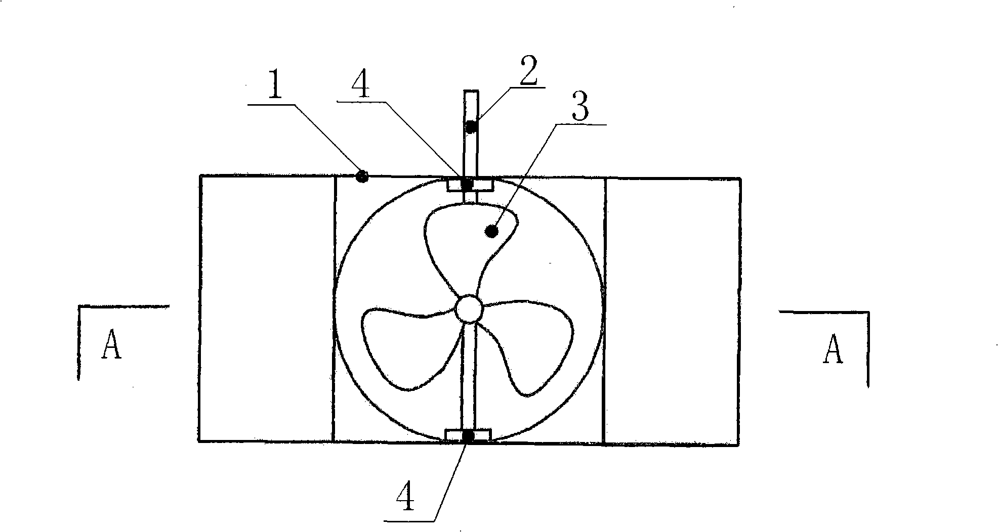
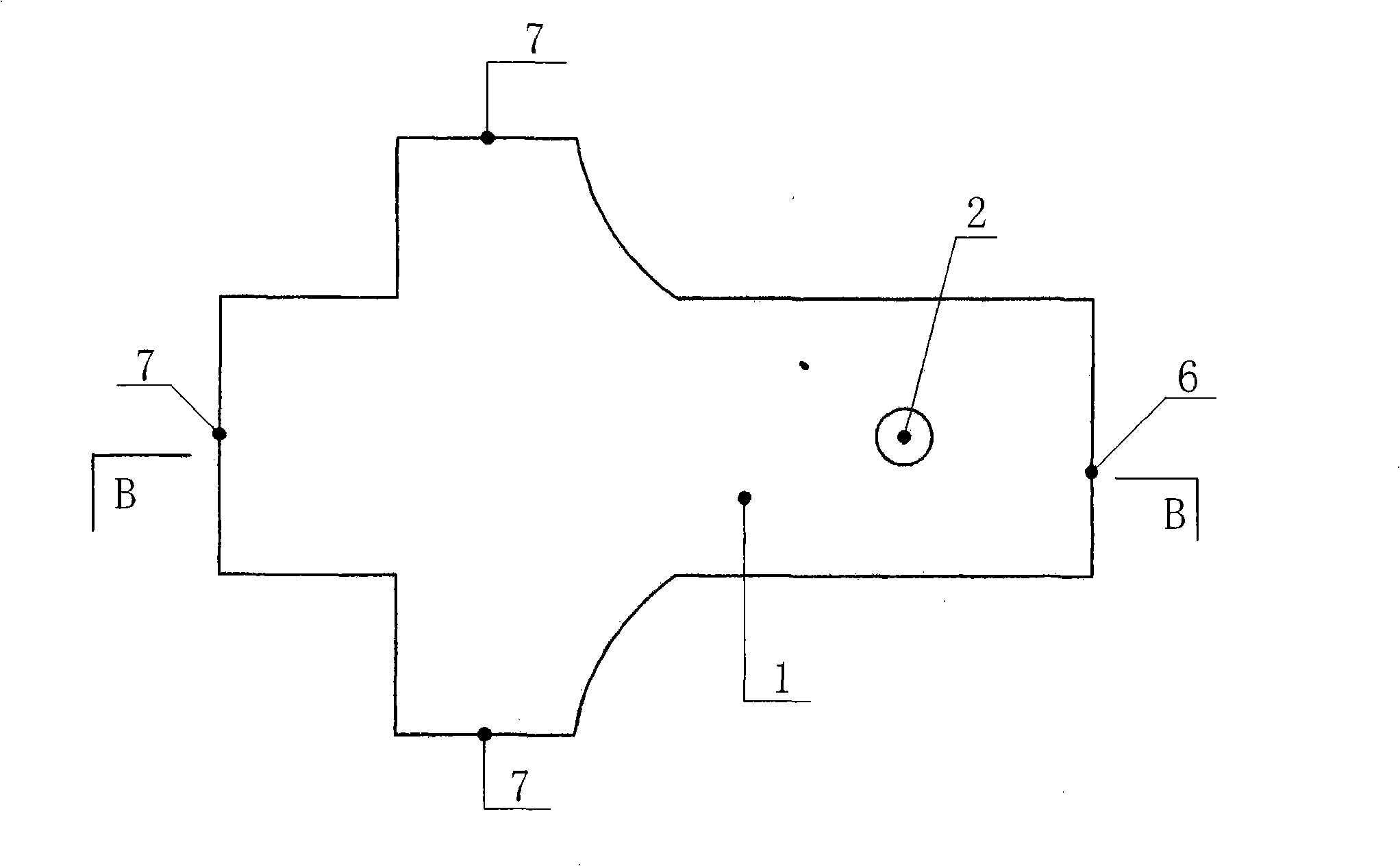
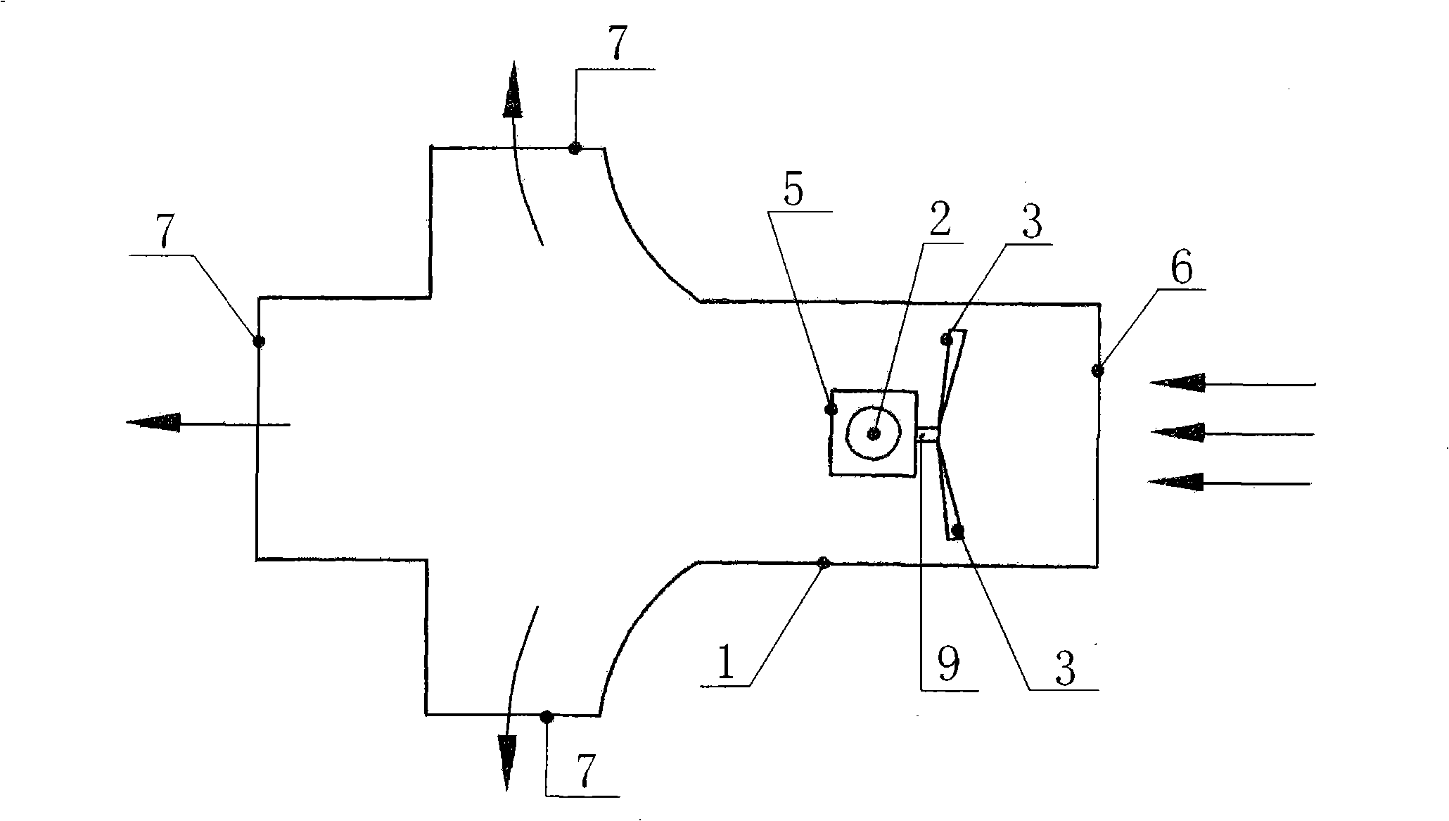
[0032] figure 1 It is the elevation view of the wind tunnel airflow engine of the present invention; figure 2 It is a top view of the wind tunnel airflow engine of the present invention; image 3 is the invention figure 1 The A-A section view of the wind tunnel airflow engine in ; Figure 4 is the invention figure 2 The B-B cross-sectional view of the wind tunnel airflow engine in ; Figure 5 It is a top view of the wind tunnel airflow generator of the present invention; Image 6 It is the elevation view of the wind tunnel airflow generator of the present invention; Figure 7 is the invention Image 6 The C-C cross-sectional view of the wind tunnel air generator in .

[0033] In the figure: 1, wind tunnel, 2, transmission shaft, 3, blade, 4, bearing, 5, transmission gear set, 6, wind tunnel air inlet, 7, wind tunnel air outlet, 8, generator, 9, impeller shaft.

[0034]The wind tunnel airflow engine of the present invention is made up of the wind tunnel 1 that is use...


PUM


Abstract

The present invention relates to a wind tunnel airflow engine, a wind tunnel airflow generator and application thereof. The wind tunnel airflow engine comprises a wind tunnel and an airflow engine which are mounted in wind tunnel by bearing; the hull of wind tunnel is rigidity channel which consisting of an air inlet and air outlet on two sides and tail part, the air outlets on two sides of wind tunnel extend outward as airplane wings from two sides of tunnel; the airflow engine device is provided in the space of air inlet and air outlet of wind tunnel. The present invention using wind tunnel can produce positive and negative pressure at air inlet and outlet to cause airflow in tunnel do work and the power is higher than power produced by airflow outside the tunnel, airflow engine device of generator mounted in wind tunnel make the generate power of wind tunnel airflow generator is higher than power of wind power generator in environment, the energy conversion rate is enhanced and the airflow generator is not effected by change of nature wind power, wind direction, and the application range is wide.

Description

technical field [0001] The invention relates to a wind tunnel airflow engine which uses the airflow in the wind tunnel as the driving force to generate mechanical energy, and the wind tunnel airflow generator which uses the wind tunnel airflow engine as the driving force and its application. Background technique [0002] The technology of converting wind energy into mechanical energy and electrical energy by using the positive air pressure generated by gas flow has been widely used, such as windmills and natural wind generators. However, there are the following defects in the traditional wind energy utilization technology: ① only the energy generated by the positive pressure formed by the natural air flow is used, and the energy of the negative air pressure that the air flow can generate under certain conditions to form a pulling force on the material is not fully utilized. Utilization and conversion; ②In the current utilization of wind energy, people mainly use the energy g...

Claims


Application Information

Patent Timeline
Patent Type & Authority Applications(China)
IPC IPC(8): F03D1/00F03D1/06F03D1/04F03D9/00B60L8/00H02K53/00F03D9/25F03D9/32
CPCY02E10/72Y02T10/64Y02T10/7072
Inventor 吴勉之
Owner 吴勉之
Why Eureka
Try Eureka