
Non-contact type tachometric sensor

A rotational speed sensor, non-contact technology, applied in instruments, linear/angular velocity measurement, velocity/acceleration/impact measurement, etc., can solve the problems of high cost, inability to directly apply, complex structure, etc., and achieve low cost, simple and reliable structure Effect

Inactive Publication Date: 2008-09-03
CHINA MINMETALS CHANGSHA MINING RES INST
View PDF1 Cites 7 Cited by
  • Summary
  • Abstract
  • Description
  • Claims
  • Application Information

AI Technical Summary

Problems solved by technology

These speed sensors can only be applied on land, but cannot be directly applied in the environment of deep-sea high-pressure high-conductivity seawater, and some have complex structures and high costs. Various deep-sea electromechanical equipment, such as underwater engineering equipment, submarines, Underwater samplers, underwater workstations, etc. often need to use speed sensors to measure the speed of rotating parts
In the prior art, there is no report of a non-contact speed sensor that can measure the rotational speed of various electromechanical equipment rotating parts, and is especially suitable for measuring the rotational speed of deep sea electromechanical equipment rotating parts.

Method used


Image

  • Non-contact type tachometric sensor
  • Non-contact type tachometric sensor
  • Non-contact type tachometric sensor

Examples


Embodiment 1

[0016] Embodiment 1: Used to measure the rotational speed of the rotating parts of common electromechanical equipment

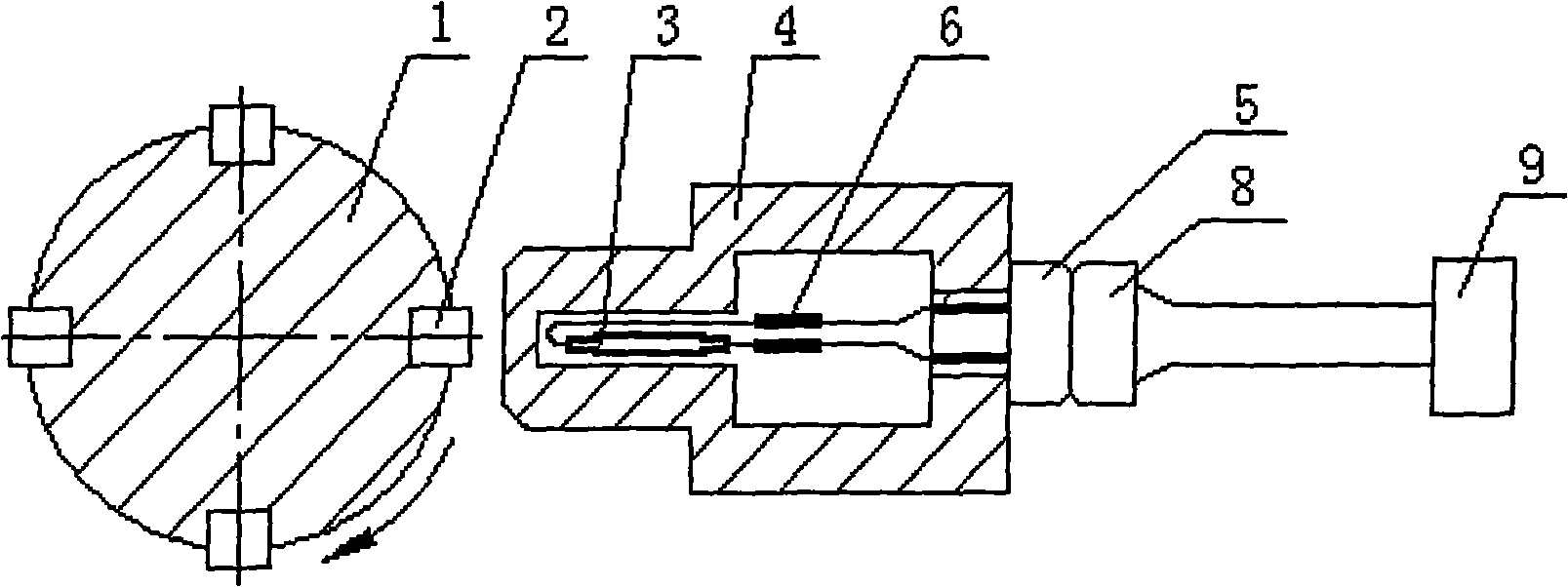
[0017] combined with figure 1 :

[0018] Four permanent magnets 2 are evenly fixed on the circumferential surface at the same axial position as the rotating shaft 1 of the measured electromechanical equipment, and the reed switch 3 is packaged at the front end of a hard plastic shell 4 with a wall thickness of 1 mm. The reed switch passes through The reed switch connection line 6 is connected to the socket 5, the socket 5 is connected to the sensor signal output cable 8, and the sensor signal output cable is connected to the switching frequency measurement and control system circuit 9 in the prior art. Due to the rotation of the measured rotating shaft 1, when the permanent magnet 2 is close to the magnetic reed switch 3, the magnetic reed switch 3 will feel the action of the magnetic field and close; when the permanent magnet leaves the magnetic reed switch...

Embodiment 2

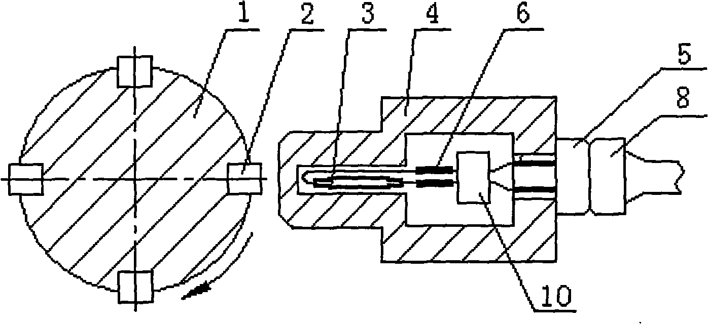
[0020] combined with figure 2 : Different from Embodiment 1: after the reed switch connection line 6 is connected with the signal preprocessing circuit 10 in the prior art, it is connected with the socket 5 again.

Embodiment 3

[0021] Embodiment 3: It is used to measure the rotational speed of the drill pipe of a deep-sea core sampling drilling rig.

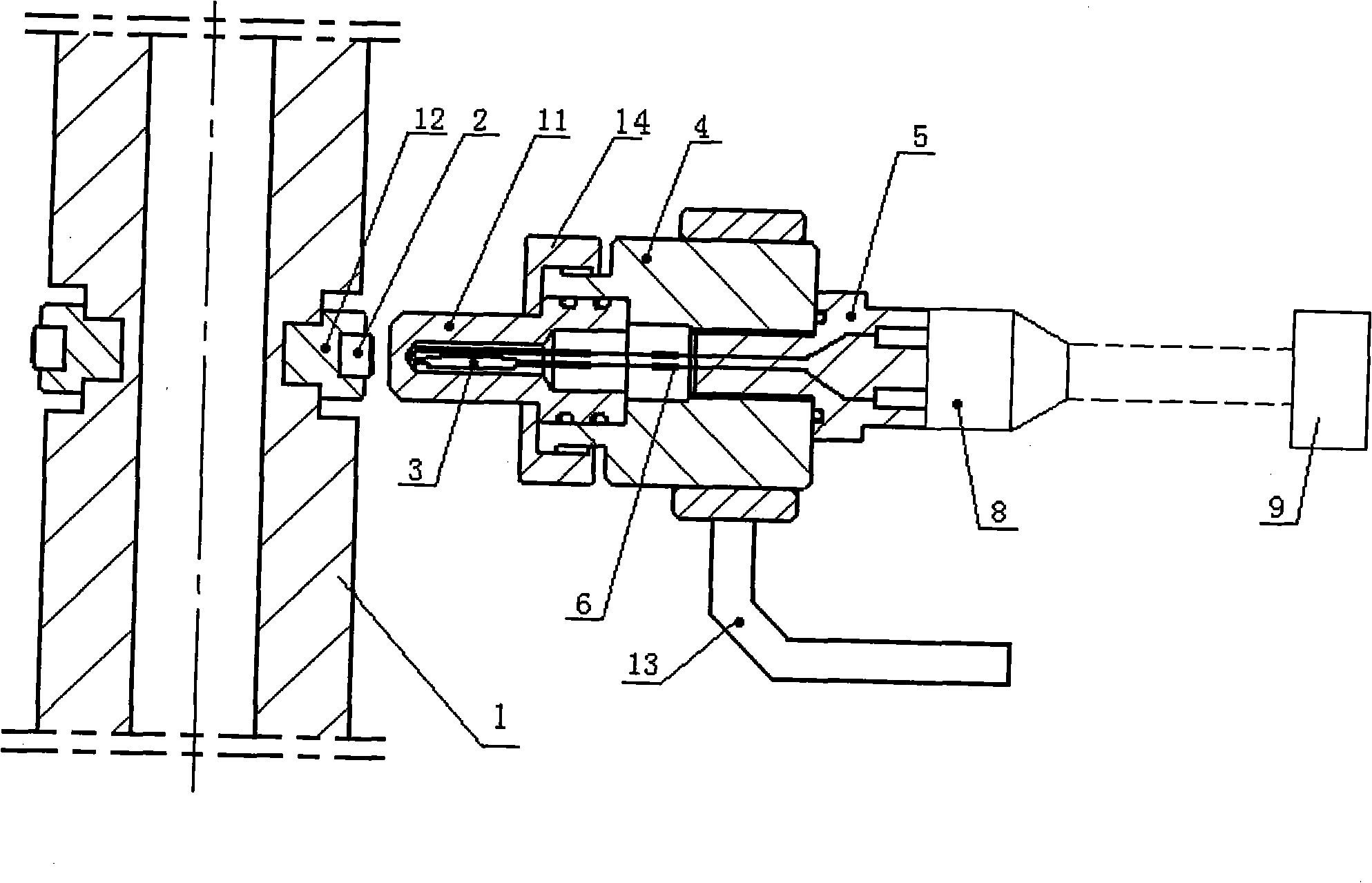
[0022] combined with image 3 :

[0023] The difference from Embodiment 1 is that the housing is composed of several pressure-resistant parts, and a reed switch 3 is packaged in a part at the front end to form a pressure-resistant reed switch sleeve 11, which is cylindrical in shape and pressure-resistant. The cylindrical tail end of the reed switch cover is inserted into the hole at the front of the pressure-resistant housing 4, and is sealed by the sealing ring 7, and the pressure-resistant dry reed switch cover 11 and the pressure-resistant housing 4 are locked and fixed by the lock nut 14 again. A sealing ring 7 is provided at the connection of each part. The reed switch connection line 6 is connected with the deep seawatertight socket 5 with the sealing ring 7, and the sensor signal output cable 8 has a watertight plug suitable for the deepwatert...


PUM


Abstract

The invention discloses a non-contact revolution speed transducer, comprising a non-magnetic material shell with magnetoconductivity; a dry reed pipe sealed on the front end of the shell and connected with sensor signal output cable by connecting line of dry reed pipe; 1-N permanent magnets for controlling the switch of the dry reed pipe circuit being fixed on rotation axis surface of the motor to be measured. The structure is simple and the cost is low. The running of the rotation axis is not affected. The non-contact revolution speed transducer can measure rotate speed of rotational parts of a great variety of motors, especially used in abyssal environment and measure the rotate speed of rotational parts of abyssal motor.

Description

technical field [0001] The invention relates to a non-contact speed sensor capable of measuring the speed of rotating parts of various electromechanical equipment, in particular a non-contact speed sensor suitable for measuring the speed of rotating parts of deep sea electromechanical equipment. Background technique [0002] There are some rotational speed sensors in the prior art, such as a nano-magnetic sensitive rotational speed sensor disclosed in 200310108098.4, which is mainly used for wheel machine equipment, motors, especially automobile wheel rotational speed sensing and detection. These speed sensors can only be applied on land, but cannot be directly applied in the environment of deep-sea high-pressure high-conductivity seawater, and some have complex structures and high costs. Various deep-sea electromechanical equipment, such as underwater engineering equipment, submarines, Underwater samplers, underwater workstations, etc. often need to use speed sensors to mea...

Claims


Application Information

Patent Timeline
Patent Type & Authority Applications(China)
IPC IPC(8): G01P3/481H01H36/00
Inventor 万步炎黄筱军
Owner CHINA MINMETALS CHANGSHA MINING RES INST
Learn More