

Driving mechanism and cutting apparatus
A technology of driving mechanism and driving part, which is applied to fine working devices, mechanical equipment, shafts and bearings, etc. It can solve problems such as damage to the feed screw shaft 102, decline in chip quality, wafer vibration, etc., and achieve improved vibration absorption effect , improved stability, and fast rotation effects
- Summary
- Abstract
- Description
- Claims
- Application Information
AI Technical Summary
Problems solved by technology
Method used
Image

Examples
Embodiment Construction
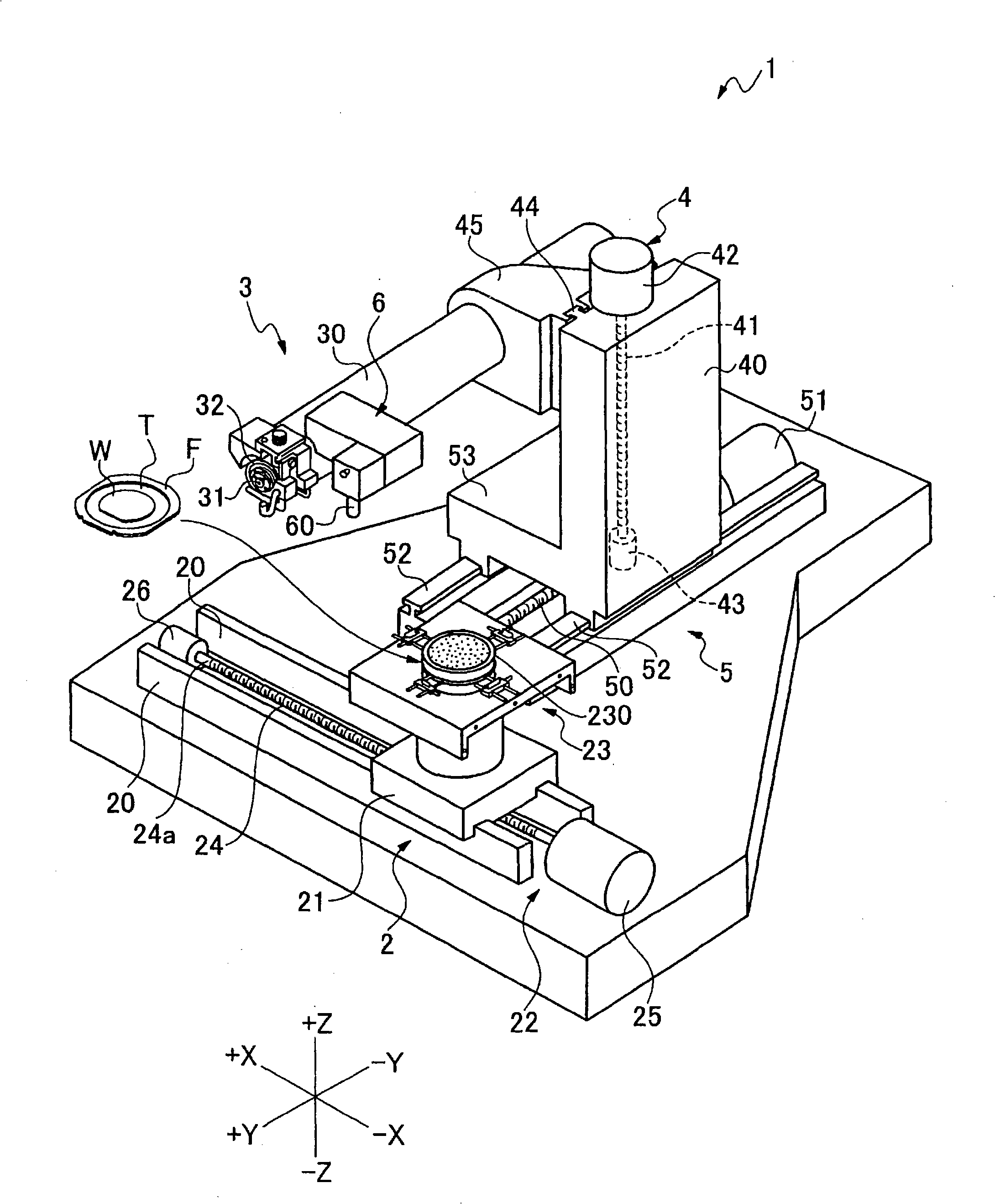
[0029] figure 1 The cutting device 1 shown is a device for cutting various workpieces, and it has at least a drive mechanism 2 which has a function for moving a chuck table 23 holding the workpiece.
[0030] The driving mechanism 2 is composed of the following components: a pair of guide rails 20 arranged in the X-axis direction; a sliding body 21 that is engaged with the guide rail 20 and slidable; a driving part 22 that moves the sliding body 21 along the guide rail 20; A chuck table 23 on the sliding body 21 as an action unit.
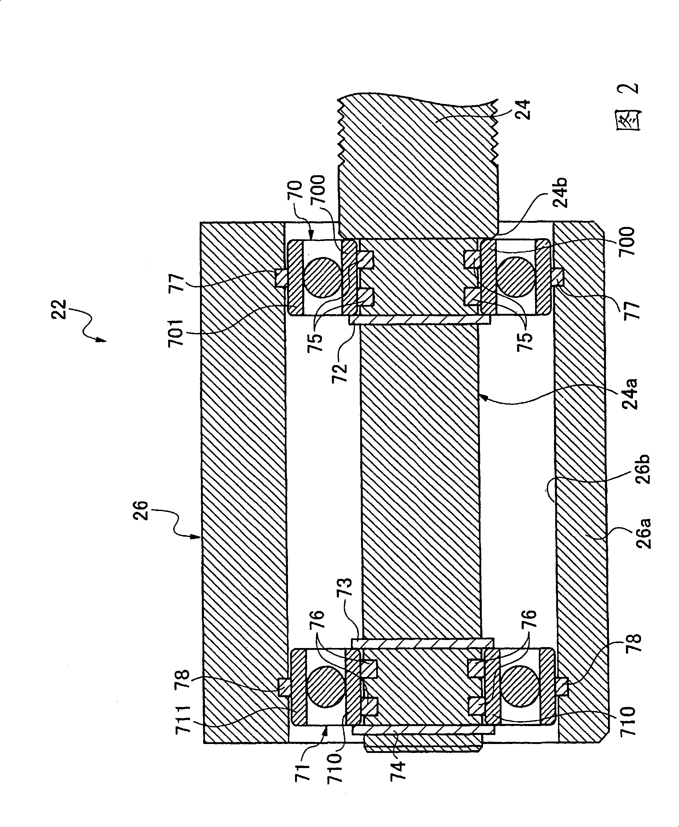
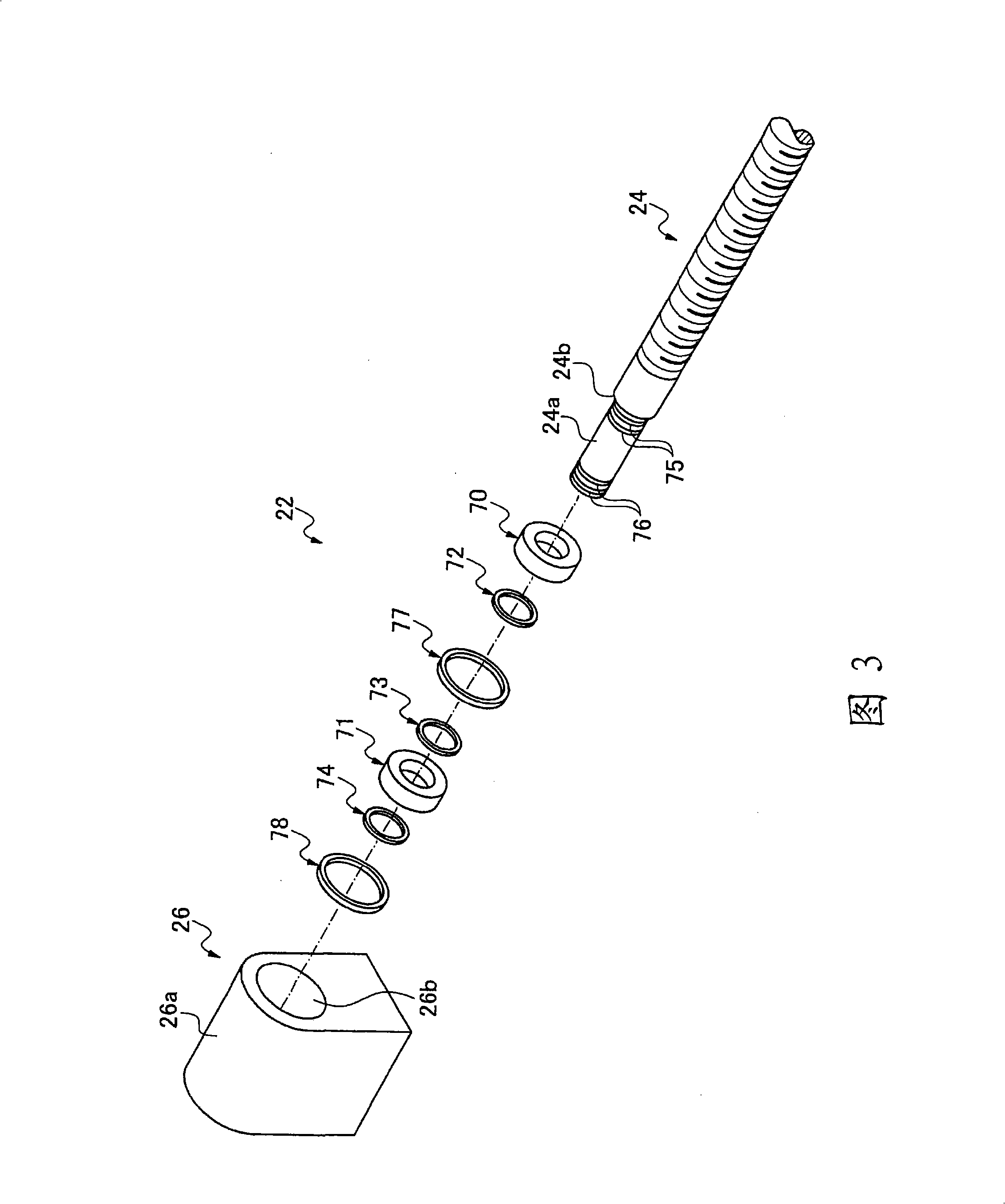
[0031]The drive unit 22 has: a feed screw shaft 24 arranged in parallel with the guide rail 20; a drive source 25 connected to one end of the feed screw shaft 24 and rotates the feed screw shaft 24; and the feed screw shaft 24 The free end 24a is supported as a rotatable end support 26; a feed nut (not shown) screwed on the feed screw shaft 24 and connected to the chuck table 23 as an action unit through a sliding body 21 ). The driving part 22 is of s...
PUM
 Abstract
Description
Claims
Application Information