
Dust removing equipment

A technology for dust removal equipment and dust collection chambers, which is applied to the separation of dispersed particles, chemical instruments and methods, combined devices, etc., can solve the problems of complicated pipelines, large floor space, air flow path restrictions, etc., and achieves simple internal structure and construction. Low-cost, widely applicable effects

Inactive Publication Date: 2011-04-27
倪如宝
View PDF0 Cites 1 Cited by
  • Summary
  • Abstract
  • Description
  • Claims
  • Application Information

AI Technical Summary

Problems solved by technology

However, the conventional multi-stage series dust removal method requires a large area of ​​equipment, complex pipelines, and limited airflow paths, making it difficult to obtain better dust removal effects.

Method used


Image

  • Dust removing equipment
  • Dust removing equipment
  • Dust removing equipment

Examples


Embodiment Construction

[0016] The specific embodiment of the present invention is described below in conjunction with accompanying drawing:

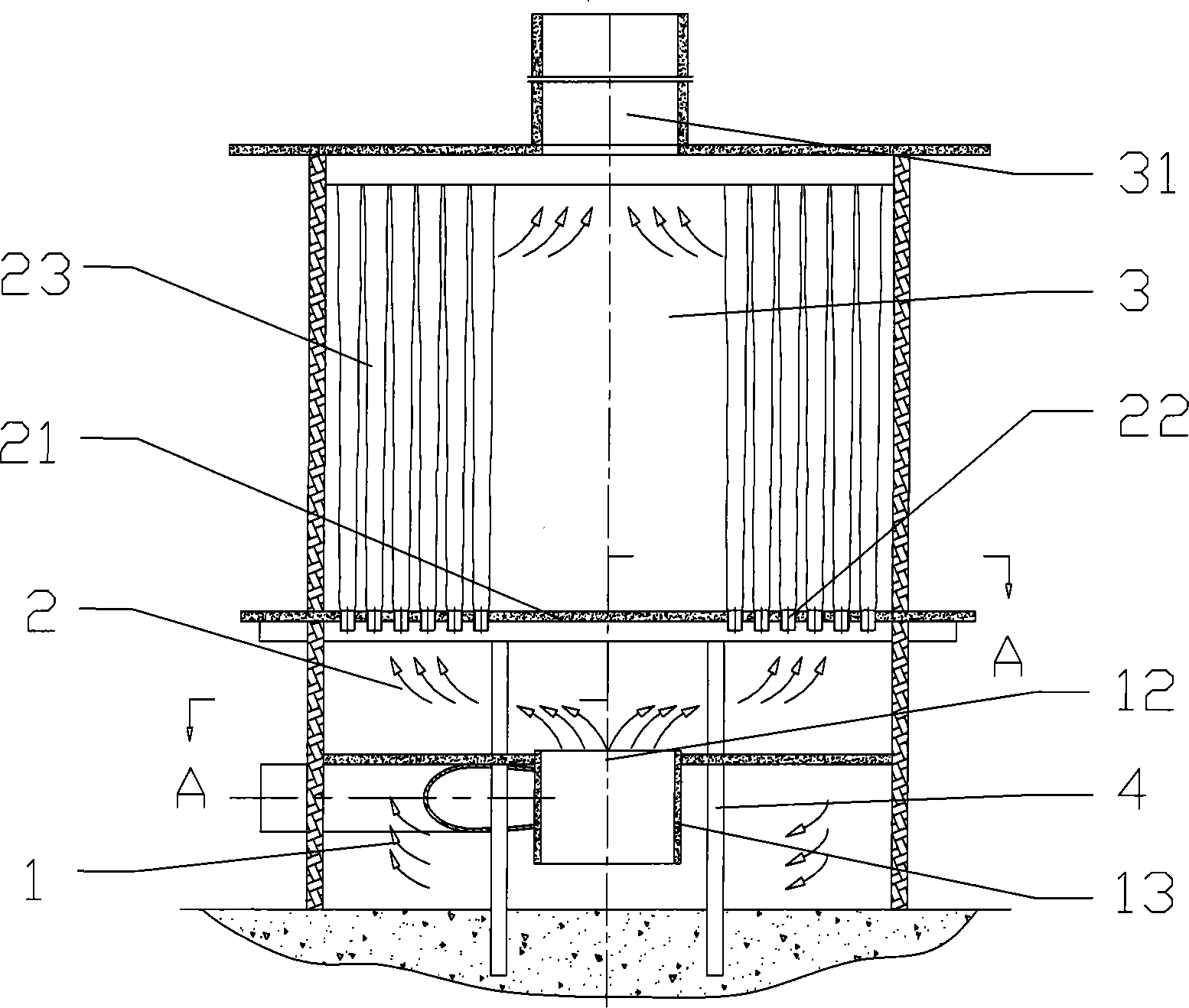
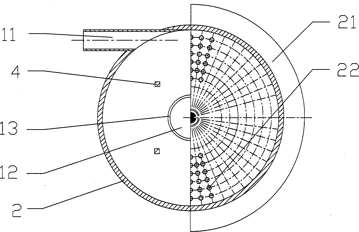
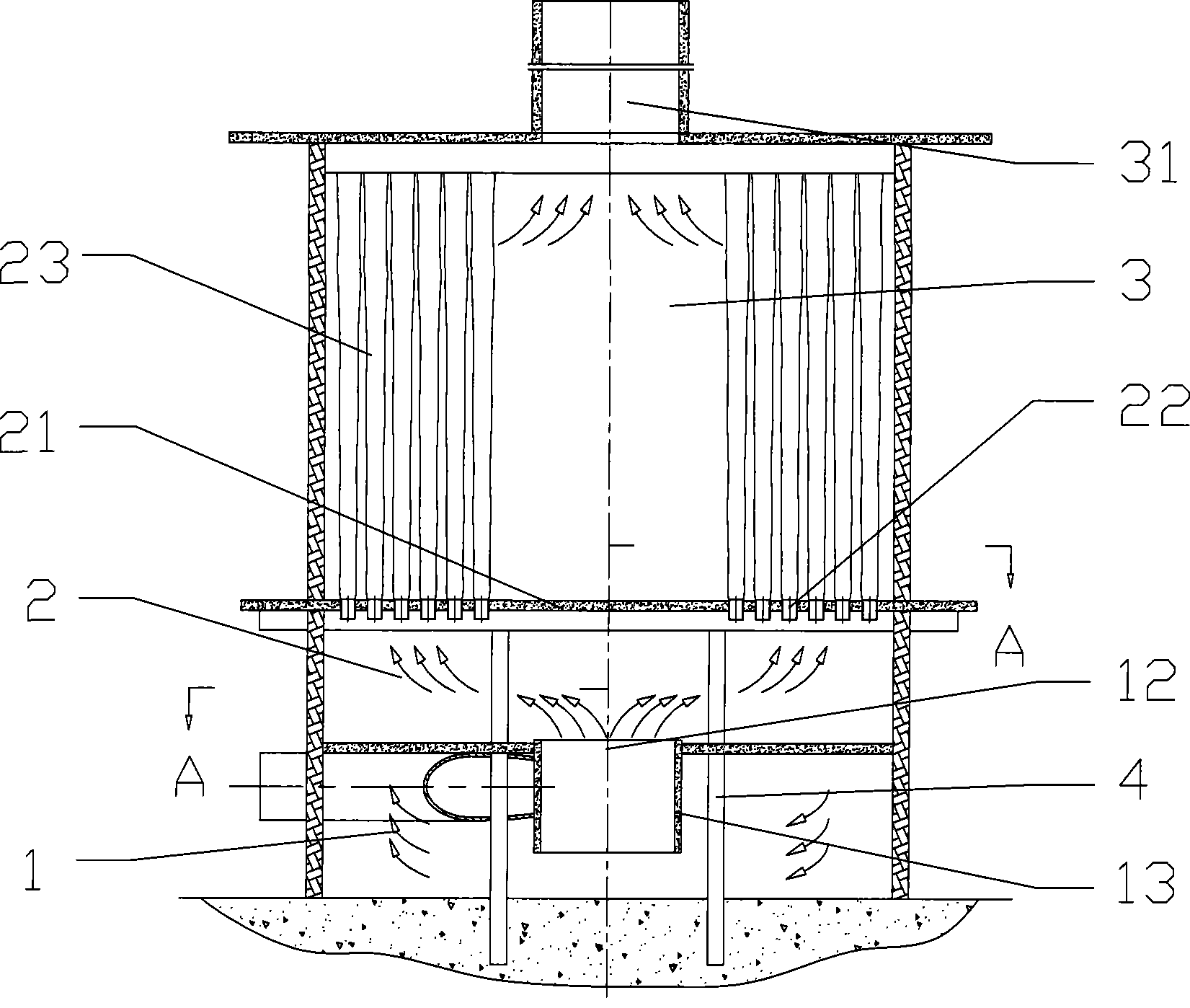
[0017] The dust removal equipment implemented according to the present invention includes a cyclone chamber 1 for cyclone dust removal, a diffusion chamber 2 for static dust removal, and a baghouse 3 for baghouse dust removal from bottom to top.

[0018] as attached figure 1 And attached figure 2 As shown, the dust removal equipment is an upright cylindrical shape with a total height of 13 meters and a diameter of 10 meters, and its bottom end is a cyclone chamber 1 with a height of 3 meters. An inlet passage 11 is opened on the side wall of the cyclone chamber 1, and a circular outlet passage 12 is opened in the middle of the top wall. A cylinder 13 with a height of 2 meters and a diameter of 2 meters extends downward from the top wall at the edge of the outlet passage 12 .

[0019] The diffusion chamber 2 located above the cyclone chamber 1 is 2 meters h...


PUM

PropertyMeasurementUnit
diameteraaaaaaaaaa
diameteraaaaaaaaaa
diameteraaaaaaaaaa

Abstract

The invention discloses a dust removing equipment, which comprises the following parts from down and up: a cyclone chamber used for cyclone type dusting, a diffuser chamber used for static dusting and a bag room used for bag type dusting. A three-grade dusting can be realized by connecting the three dusting devices in series. According to a dust removal system implemented in the invention, the dusting efficiency is as high as 99.5 percent; the flue gas exhausted from an outlet of cleaning air contains no more solid dust particles which can be directly discharged into atmosphere and reaches the state environment protection standards. Meanwhile, the dust removal system has advantages of simple inner structure, comparatively low construction cost, which can be widely applied to dust removingwork of various delivery capacities.

Description

technical field [0001] The invention relates to a dust removal device for removing solid dust particles in flue gas. Background technique [0002] In the prior art, there are mainly two methods for removing solid dust particles mixed in flue gas, cyclone dust removal and bag dust removal. Using any one dust removal method alone can not achieve particularly high dust removal efficiency. Generally, the two dust removal methods are connected in series to form a multi-stage method to obtain a good dust removal effect. However, the conventional multi-stage series dedusting method has a large area of ​​equipment, complicated pipelines, and restricted air flow paths, making it difficult to obtain a better dedusting effect. Contents of the invention [0003] The object of the present invention is to provide a dust removal device with high dust removal efficiency. [0004] The technical scheme that the present invention takes is: [0005] A kind of dust removal equipment, compr...

Claims


Application Information

Patent Timeline
Patent Type & Authority Patents(China)
IPC IPC(8): B01D50/00
Inventor 倪如宝姬高生
Owner 倪如宝
Learn More