
Multi- lens measurement method

A measurement method and multi-lens technology, applied in the field of measurement, to achieve high measurement accuracy, improve measurement speed and efficiency, and reduce movement and focusing effects

Active Publication Date: 2008-09-10
HEXAGON METROLOGY SPA
View PDF1 Cites 7 Cited by
  • Summary
  • Abstract
  • Description
  • Claims
  • Application Information

AI Technical Summary

Problems solved by technology

[0004] The purpose of the present invention is to provide a multi-lens measurement method, which overcomes the defects of existing single-lens measurement, and is easy to operate and fast in measurement speed

Method used


Image

  • Multi- lens measurement method
  • Multi- lens measurement method

Examples


Embodiment 1

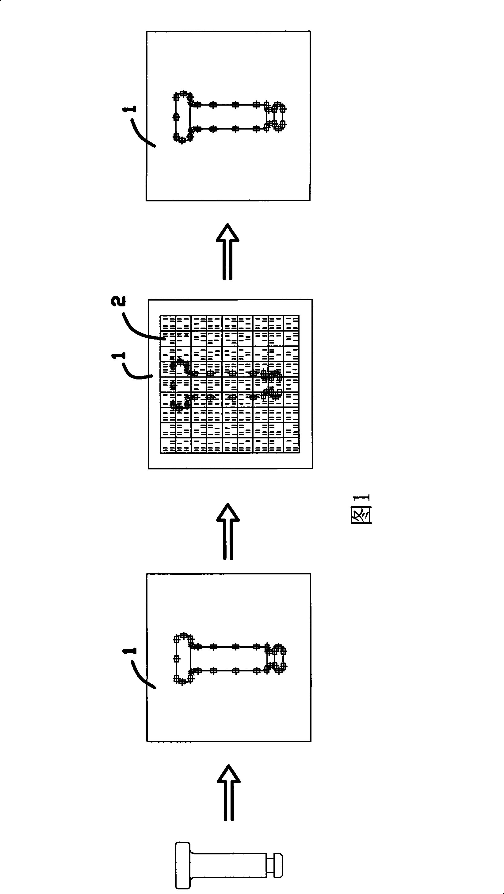
[0025] As shown in Figure 1, to measure the plane parameters of the "T"-shaped workpiece shown in the figure, the first step is to take out a sample workpiece (one sample workpiece can be randomly taken out of all workpieces), and the sample workpiece is placed on the measuring platform 1. Each measuring lens is aimed at the distribution of different measuring parts of the measured object (model workpiece), and each measuring lens is fixed after adjustment; then the sample workpiece is removed, and a grid coordinate plate 2 is inserted on the measuring platform 1, according to the network The grid coordinate plate 2 constructs a reference coordinate system. At this time, the focal points of a plurality of measuring lenses respectively establish a coordinate in the coordinate system, which is recorded as a reference point and stored in the computer; the reference point is a reference point for conversion Measure the actual coordinates of other measured objects; the measurement l...

Embodiment 2

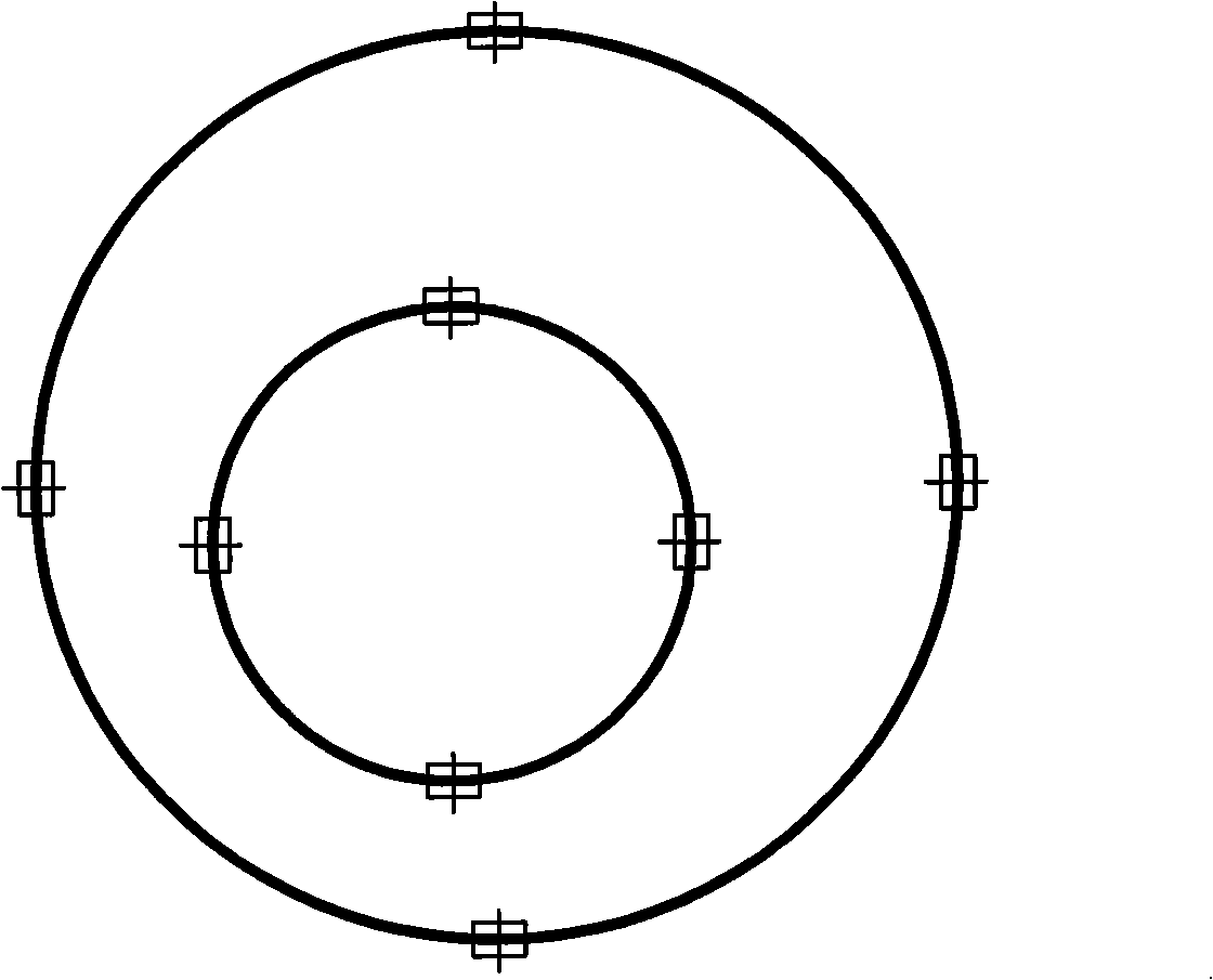
[0028] Such as figure 2 As shown, when measuring the concentricity, multiple measurement arrays are distributed on the inner and outer circumferences to measure simultaneously, and the actual inner and outer circumferences can be determined according to the actual coordinate parameters, so that the concentricity of the inner and outer circles can be further determined.

[0029] Of course, the scope of application of the present invention is not limited to the above-mentioned embodiments, and it can also be used for measurement of irregular lines, surfaces, angles or radians, and also for stereo measurement. For stereo measurement, the lens can be erected or placed horizontally Or set it obliquely, so as to obtain a three-dimensional distribution and meet the measurement requirements. The present invention provides a measurement concept, which is different from single-lens measurement, obtains a better measurement method, and promotes the development of measurement technology. ...


PUM


Abstract

The invention relates to the measurement technical field, in particular to a measurement method. The measurement method comprises the steps as follows: (1) a plurality of measurement lenses are distributed by aiming at different measurement positions of an object to be measured, and all measurement lenses are fixed after being aligned; (2) the object to be measured is moved away, a grid coordinate plate is inserted, and a plurality of measurement lenses are respectively corresponding to a coordinate in the coordinate system which is marked as a datum point; (3) the grid coordinate plate is moved away, another object of the same kind to be measured is arranged on the measurement platform, a plurality of measurement lenses automatically focus on the article to be measured, and the practical coordinate of the practical measurement position of the article to be measured is converted by the datum coordinate of the measurement lenses; (4) a planar profile or a solid profile of the object to be measured is virtually configured in a micro-computer according to the gained practical coordinate, thus gaining the practical parameters of the object to be measured and memorizing the practical parameters into the micro-computer. The measurement method replaces the single-lens movement of single-lens with that of the multi-lens movement, reduces the operation of movement and focusing, improves the measurement speed, and eliminates the mechanical errors which are caused by movement.

Description

Technical field: [0001] The invention relates to the technical field of measurement, in particular to a measurement method. Background technique: [0002] In the prior art, generally, a single camera is used to move and capture the measuring part of the measured object, and combined with a microcomputer to construct the measured object virtually, so as to obtain the technical parameters of the measured object in plane or three dimensions. However, in actual measurement, moving the lens is quite time-consuming and troublesome, and every time the lens is moved, focus adjustment is required, and the measurement efficiency is low. [0003] This case is proposed on the basis of the patent technology previously owned by the applicant, and further proposes this measurement method by using the measurement technology in the patent ZL02248568.6. Invention content: [0004] The purpose of the present invention is to provide a multi-lens measurement method, which overcomes the defect...

Claims


Application Information

Patent Timeline
Patent Type & Authority Applications(China)
IPC IPC(8): G01B11/00G01B11/24G01B11/26
Inventor 徐春云
Owner HEXAGON METROLOGY SPA
Learn More