Movable central positioning feeding numerical control shearing machine

A center positioning and shearing machine technology, applied in positioning devices, shearing devices, accessories of shearing machines, etc., can solve the problems of affecting accuracy, laborious movement, lack of busbar positioning, etc., to improve production efficiency, reduce inconvenience, Consistent wear effect

Active Publication Date: 2013-07-24
CANWIN AUTOMATIC EQUIP CO LTD
View PDF8 Cites 20 Cited by
  • Summary
  • Abstract
  • Description
  • Claims
  • Application Information

AI Technical Summary

Problems solved by technology

The existing CNC shearing machine tools for silicon steel sheet can be roughly divided into two types: the first one is that the feeding mechanism is fixed, the feeding roller is long, the material is positioned on the side of the cutting channel, the punching section can be moved, and the shearing machine is fixed. Yes, it has a reference busbar, which is convenient for debugging; the disadvantage is that the long side part of the feed roller is partially worn for a long time, which affects the accuracy; the quality of the feed roller is large, and when the feed roller starts and brakes at high speed, its inertia is large, and high-speed feeding is not accurate.
The second is that the feeding mechanism is fixed, centrally positioned, short feeding rollers, the material is centrally positioned on the shearing channel, the punching section can be moved, the +45° and -45° shearing section is fixed on the slide plate, and the shearing section is also The overall movement has the advantages of central positioning feeding, the feeding roller is not easy to wear, the feeding roller is light in weight, small in inertia, and high-speed feeding is accurate; the disadvantage is that it lacks busbar positioning. According to materials of different widths, the material channel must be based on the center line. To adjust on both sides, the shearer section must be moved as a whole. Since the weight of the shearer section is about 1-2 tons, it is very laborious to move, which is very unreasonable

Method used


Image

  • Movable central positioning feeding numerical control shearing machine
  • Movable central positioning feeding numerical control shearing machine

Examples


Embodiment Construction

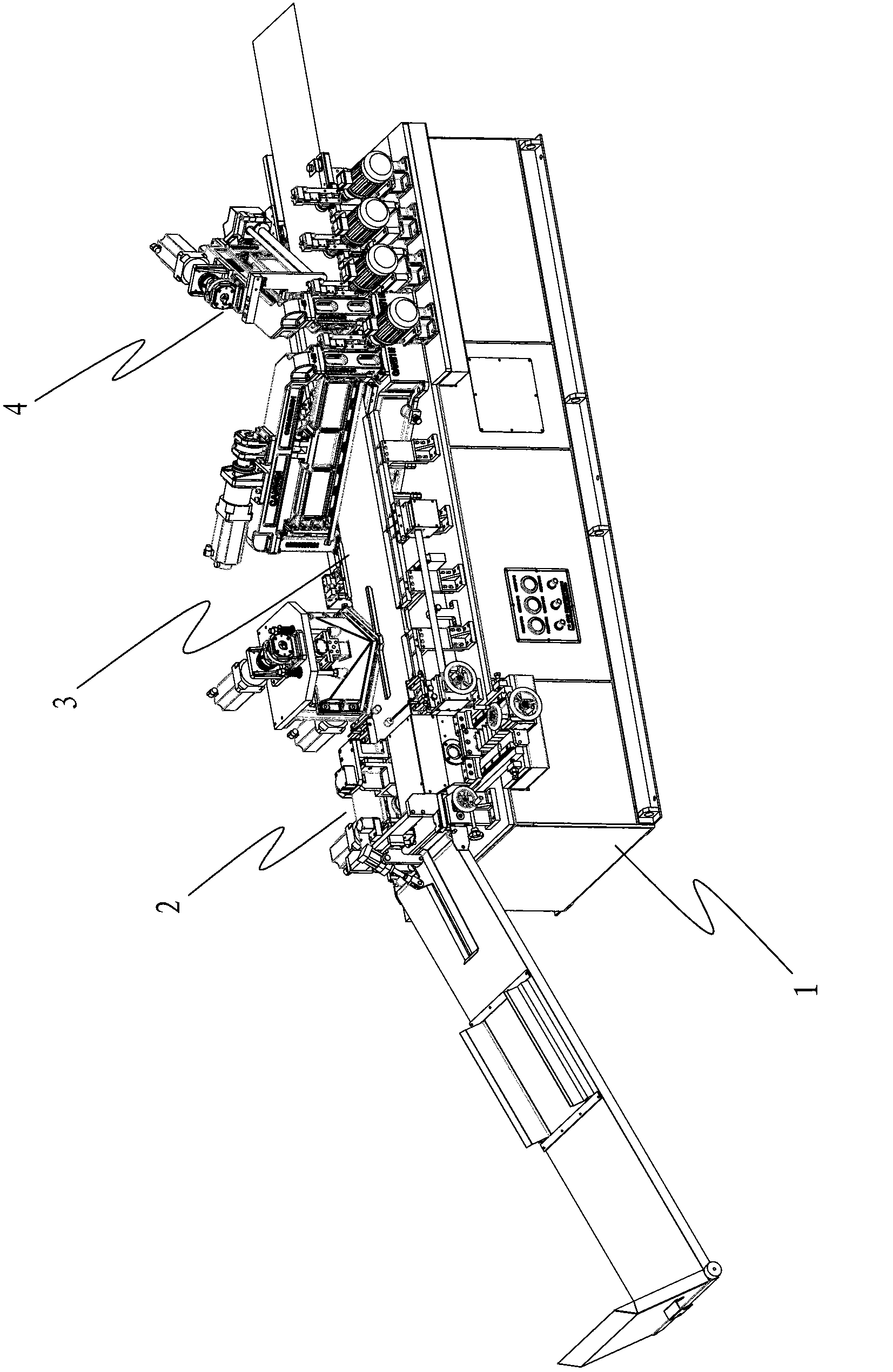
[0023] refer to figure 1 , the present invention provides a kind of numerically controlled shearing machine of movable center positioning feeding, comprising a machine base 1, a feeding mechanism 2, a conveying channel 3 and a shearing mechanism 4 are sequentially arranged on the machine base 1, and the conveying channel 3 is arranged on the feeding mechanism 2. The rear is used to convey materials. The shearing mechanism 4 is arranged above the conveying channel 3 and is used to shear the conveyed materials. According to the shape requirements of the sheared sheet, the shearing mechanism 4 can be horizontal scissors or The oblique scissors can also be used as a combination of horizontal scissors and oblique scissors.

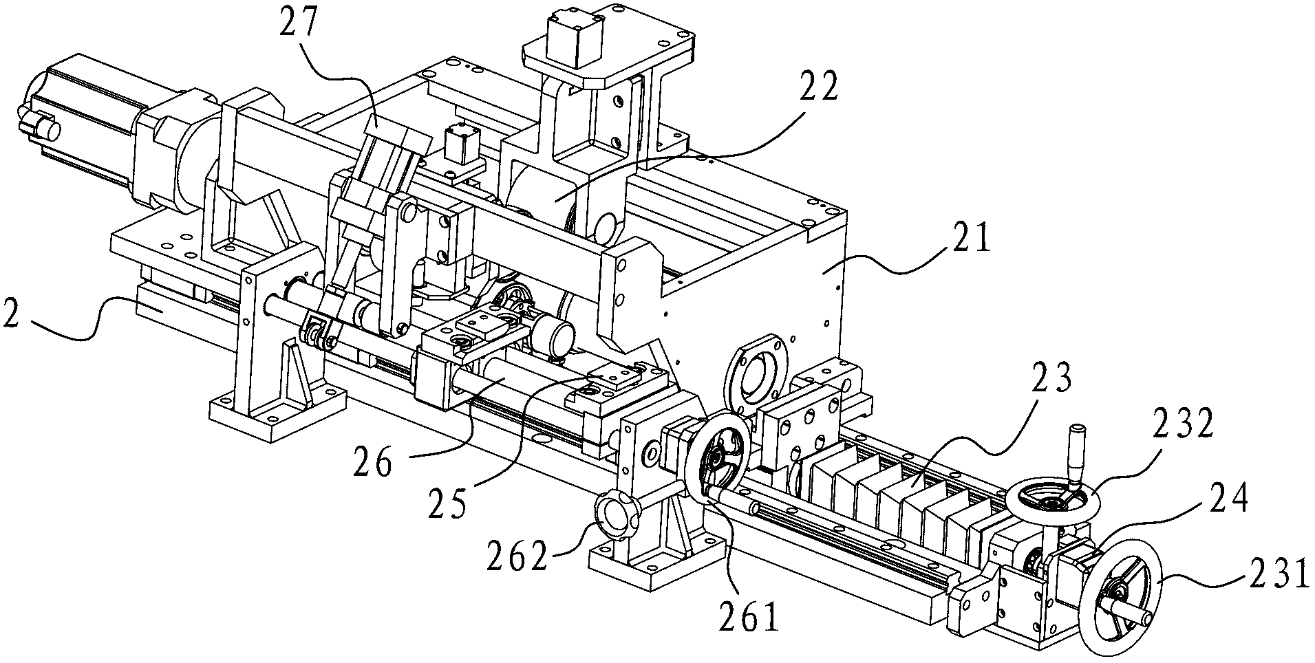
[0024] refer to figure 2 , the feeding mechanism 2 mainly includes a feeding rack 21, a motor-driven feeding wheel set 22 and a transmission screw mandrel 23, the main driving wheel of the feeding wheel set 22 in the present embodiment is made of a short feed...


PUM


Abstract

The invention discloses a movable central positioning feeding numerical control shearing machine which comprises a machine base, wherein a feeding mechanism, a conveying channel and a shearing mechanism are installed on the machine base, the feeding mechanism comprises a feeding wheel set driven by a motor, and the feeding mechanism is further provided with a transverse moving mechanism which regulates the transverse distance of the feeding wheel set; the conveying channel is installed behind the feeding mechanism, two sides of the conveying channel are provided with flanges limiting a material conveying route, and the flange on one side is fixed to serve as a material conveying base line; and the shearing mechanism comprises transverse shears and / or inclined shears which are installed above the feeding mechanism. The movable central positioning feeding numerical control shearing machine combines advantages of central positioning and single side positioning, and the feeding mechanism uses central positioning and can transversely move to conduct regulation; the conveying channel uses single side base-line positioning, and the flange on one side is fixed to serve as the base line; and when the shearing mechanism is fixed, the position of the shearing mechanism does not need to be regulated during shearing, moving inconvenience of large mechanisms can be reduced, and production efficiency is improved.

Description

technical field [0001] The invention relates to a shearing machine tool for silicon steel sheets, in particular to a movable type numerically controlled shearing machine for center positioning and feeding. Background technique [0002] The silicon steel sheet CNC shearing machine tool is mainly used for cutting the silicon steel sheet used in transformers to meet various shape requirements. The existing CNC shearing machine tools for silicon steel sheet can be roughly divided into two types: the first one is that the feeding mechanism is fixed, the feeding roller is long, the material is positioned on the side of the cutting channel, the punching section can be moved, and the shearing machine is fixed. Yes, it has a reference busbar, which is convenient for debugging; the disadvantage is that the long side part of the feed roller is partially worn for a long time, which affects the accuracy; the quality of the feed roller is large, and when the feed roller starts and brakes ...

Claims


Application Information

Patent Timeline
Patent Type & Authority Applications(China)
IPC IPC(8): B21D43/04B21D43/26B21D43/28B23D33/02
Inventor 黄健明
Owner CANWIN AUTOMATIC EQUIP CO LTD
Why Eureka
Try Eureka