Device for detachably coupling two parts
A technology of components and matching pins, which is applied in the field of connection devices, can solve problems such as material weakening, and achieve the effect of improving bending stiffness
- Summary
- Abstract
- Description
- Claims
- Application Information
AI Technical Summary
Problems solved by technology
Method used
Image

Examples
Embodiment Construction
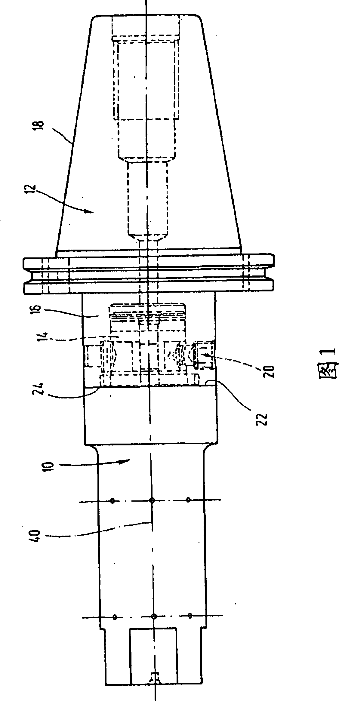
[0030]The connecting means shown in the figures are used for the detachable coupling of the components 10 , 12 . In the following, “component” is understood primarily to mean the part of the tool that contains a cooperating pin 14 or a receiving sleeve 16 . In the embodiment shown in FIG. 1, the component 10 equipped with the cooperating pin 14 is a measuring mandrel, and the component 12 provided with the receiving sleeve 16 is an adapter, which has a coupling for connection to the spindle of the machine tool. Steeply tapered shaft 18 .
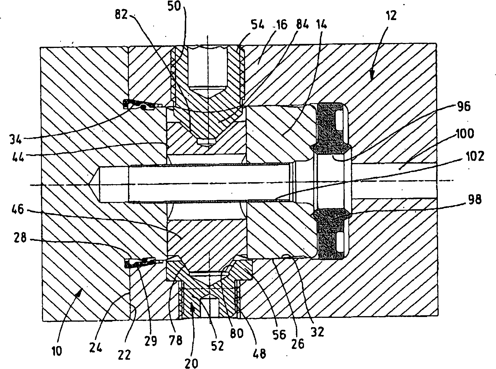
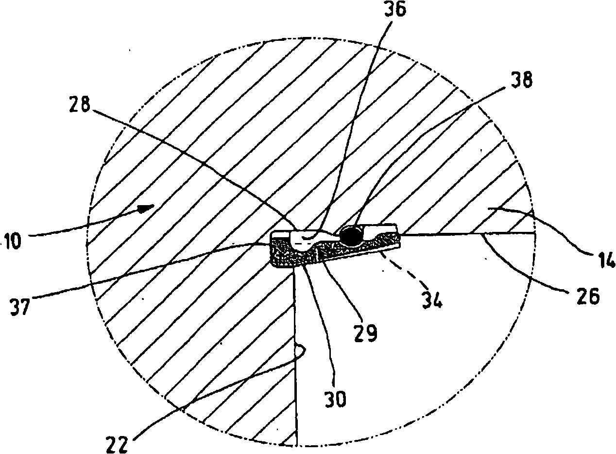
[0031] The connecting device mainly includes a mating pin 14 protruding axially on the first member 10; a receiving sleeve 16 arranged on the second member; 14 is drawn into the receiving sleeve 16 and serves to clamp in a plane between an annular plane 22 of the first component 10 delimiting the cooperating pin 14 and an end face 24 of the second component 12 delimiting the receiving sleeve 16 . The counter pin 14 has a substantially cyli...
PUM
 Abstract
Description
Claims
Application Information