Continuous burning furnace

A technology of firing furnace and cooling chamber, applied in the direction of furnace, furnace cooling, furnace type, etc., can solve the problems of warping, cooling chamber without exhaust mechanism, deformation, etc., to achieve the effect of cooling treatment

Active Publication Date: 2008-09-17
KOYO THERMO SYST CO LTD
View PDF1 Cites 7 Cited by
  • Summary
  • Abstract
  • Description
  • Claims
  • Application Information

AI Technical Summary

Problems solved by technology

[0005] However, the water-cooled fin cooler and the FFU in the cooling chamber of the continuous firing furnace in the prior art are set separately according to their respective purposes, and cannot cooperate with each other to play a role.
In addition, the cooling chamber in the prior art does not have an exhaust mechanism, but the cooling air introduced into the cooling chamber exchanges heat with the air in the cooling chamber and the glass substrate, and then flows from the supply ports formed on the side walls of the cooling chamber. Multiple through-holes for rollers discharge to the outside
External air is locally introduced into the cooling chamber from the FFU through a plurality of introduction channels. At this time, only a part of the glass substrate near the introduction channels may be rapidly cooled, resulting in local warping or deformation.

Method used


Image

  • Continuous burning furnace
  • Continuous burning furnace
  • Continuous burning furnace

Examples


Embodiment Construction

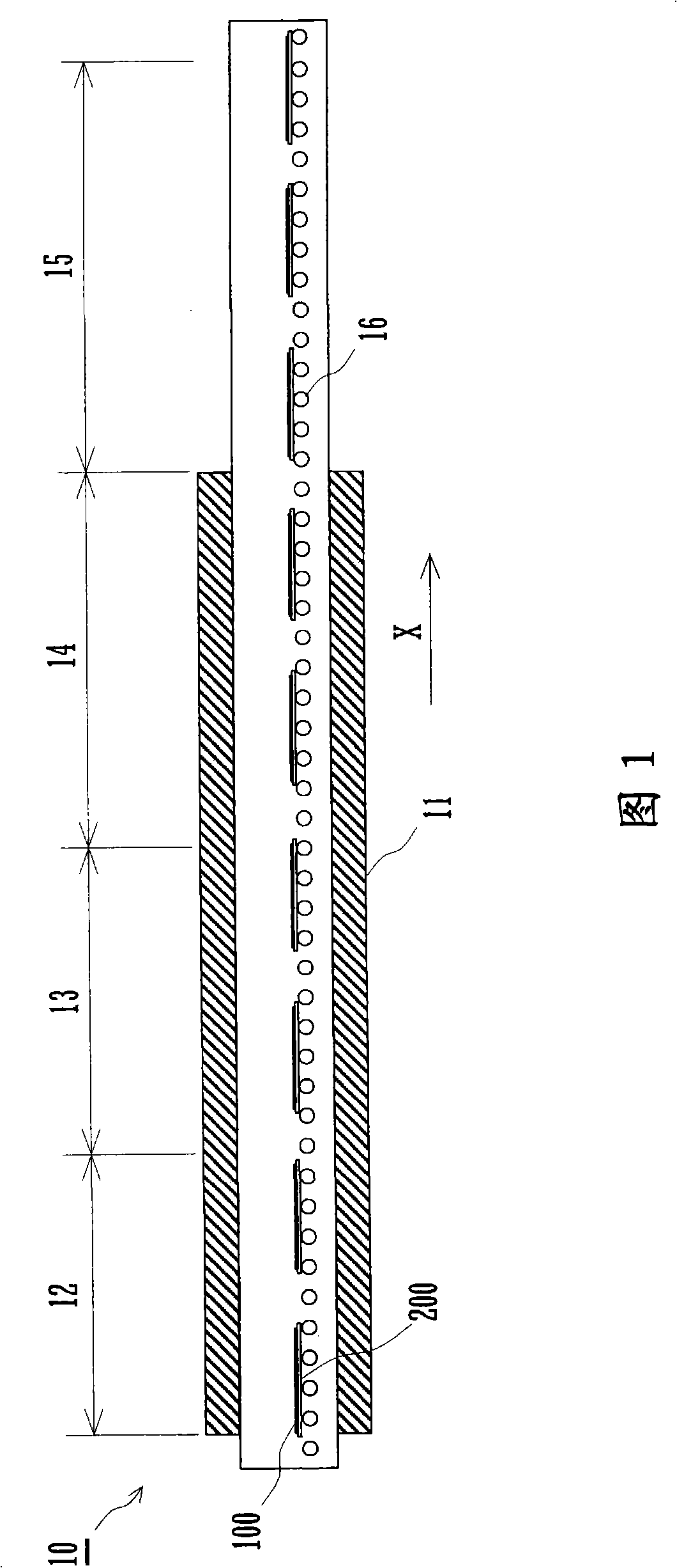
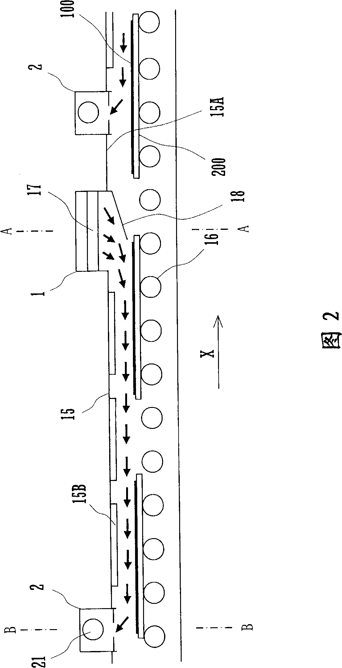
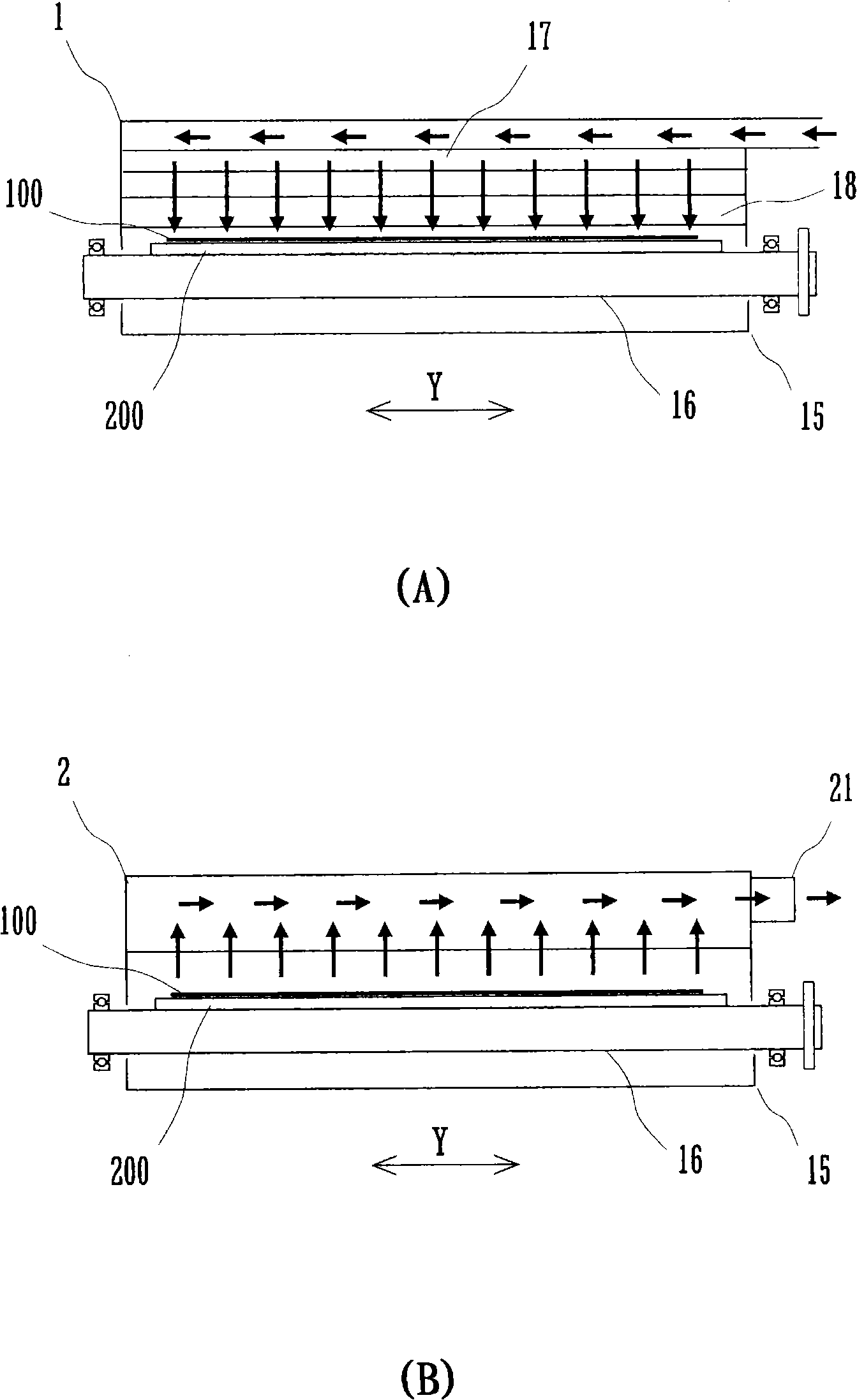
[0016] Hereinafter, specific embodiments of the present invention will be described in detail with reference to the drawings. Fig. 1 is a side sectional view showing an example of a continuous firing furnace according to an embodiment of the present invention. The continuous firing furnace 10 has a first heating chamber 12, a second heating chamber 13, and an annealing chamber 14 along the conveying direction X in the furnace 11, and the furnace 11 located on the downstream side of the annealing chamber 14 along the conveying direction X There is a cooling chamber 15 outside. In the first heating chamber 12 , the second heating chamber 13 , the annealing chamber 14 , and the cooling chamber 15 , a plurality of rotatable rollers 16 are arranged at equal intervals along the conveyance direction X.

[0017] The first heating chamber 12 performs the first temperature raising treatment and the first soaking treatment, for example, heating the treatment object to 350° C. to 400° C....


PUM


Abstract

The present invention provides a continuous firing furnace. The continuous firing furnace is able to effectively cool the whole outer surface of the processing objects such as glass substrate etc., does not generate partial warpage or deformation on the processing object and reduces the cooling processing time. The cooling chamber (15) of the continuous firing furnace (10) is installed with guiding passage (1) and exhaust passage (2). The guiding passage and exhaust passage open at the almost whole area in the furnace-width direction (Y) on the inner furnace wall (15A) at the upper side of the cooling chamber. The guiding passage ejects the air by the mode of facing to the upper reach side of the moving direction (X). The exhaust passage exhausts the air of the cooling chamber at the upper reach along the moving direction (X) of the guiding passage. On the upper part of the processing object moved on the roller (16), the flow path with cooled external gas is uniformly formed in the almost whole area on the furnace-width direction (Y). The whole upper surface of the processing object is uniformly contacted with the air.

Description

technical field [0001] The present invention relates to a continuous firing furnace for continuously performing soaking, annealing, and cooling on a processing object such as a glass substrate for a plasma display panel (PDP). Background technique [0002] The continuous firing furnace has a heating chamber and an annealing chamber inside the furnace, and a cooling chamber outside the furnace. From the heating chamber, through the annealing chamber to the cooling chamber, a conveying mechanism for continuously conveying the processing object is arranged. A conventional continuous firing furnace uses, for example, a roller hearth in which a plurality of rollers are arranged at equal intervals as a conveying mechanism. [0003] Both ends of the plurality of rollers are exposed to the outside through through holes in the side walls of the furnace and the cooling chamber, and the one end exposed to the outside is rotated by being supplied with a driving force. A glass substrat...

Claims


Application Information

Patent Timeline
Patent Type & Authority Applications(China)
IPC IPC(8): C03B25/00F27B9/12F27B9/02F27D9/00H01J9/24H01J11/22H01J11/34H01J11/36H01J11/38H01J11/42H01J11/48
CPCF27B9/045F27B9/12F27B2009/124F27D7/02F27D17/002
Inventor 山本章仁
Owner KOYO THERMO SYST CO LTD
Why Eureka
Try Eureka