

Electrode structure for electrochemical device
An electrochemical and component technology, applied in the direction of electrolysis components, electrode shape/type, electrolysis process, etc., can solve the problem of limited liquid level increase on the edge of the membrane, and achieve the effect of increasing the effective utilization area, improving the conductive effect, and reducing the contact voltage. Effect
- Summary
- Abstract
- Description
- Claims
- Application Information
AI Technical Summary
Problems solved by technology
Method used
Image

Examples
Embodiment 1
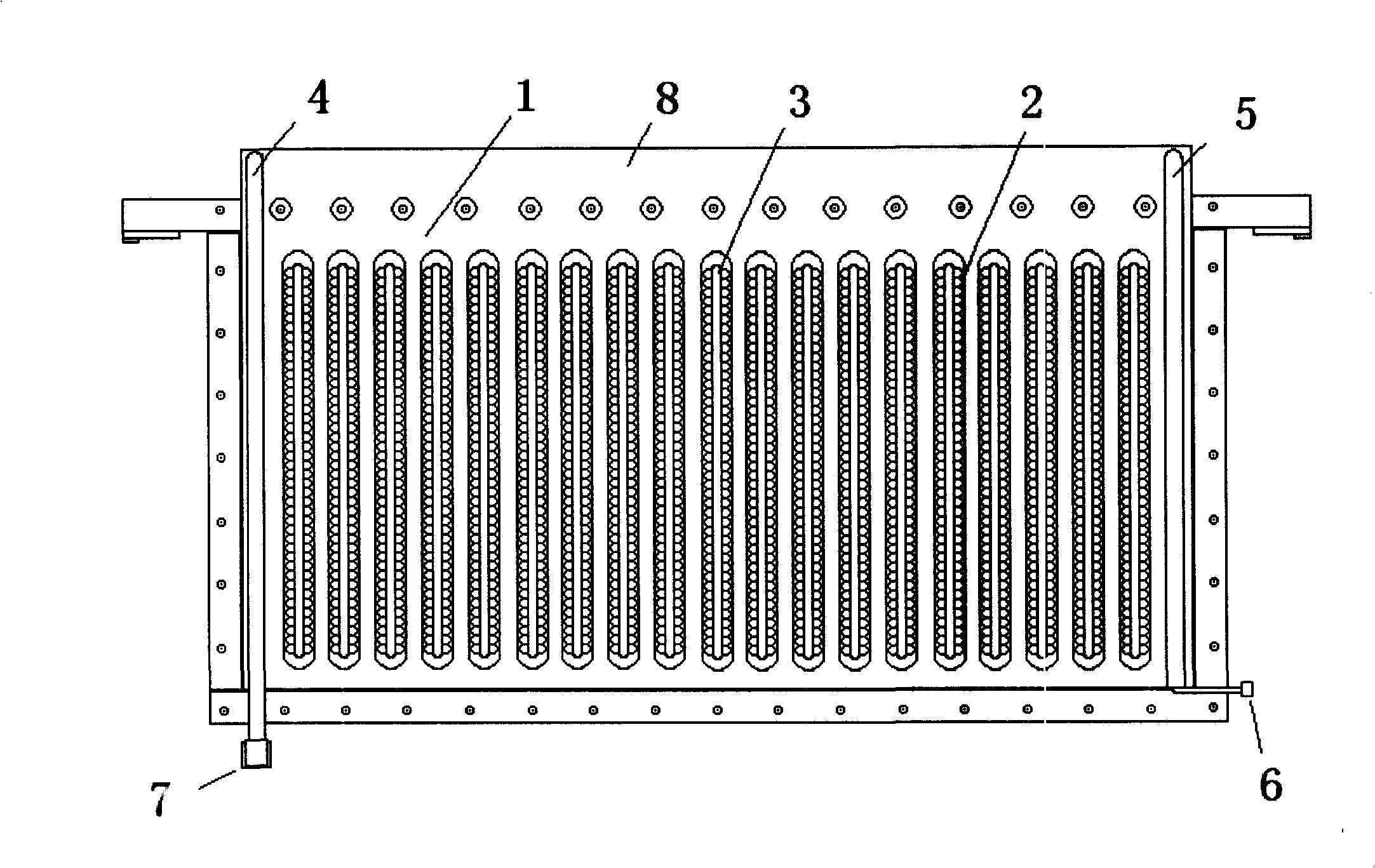
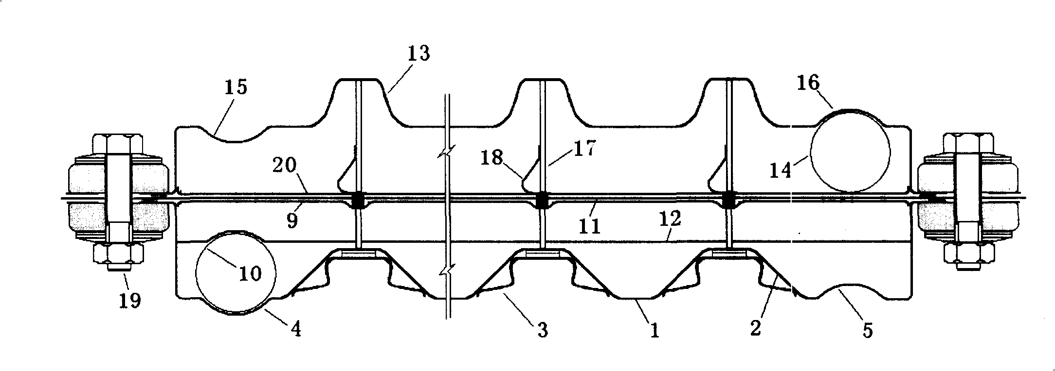
[0074] Depend on Figure 1-5 As shown, 1 in the figure is the anode tray, on the anode tray 1 there are a plurality of inwardly protruding vertically uniform guide grooves 2, on the inner wall of the guide groove welded with a bimetallic lateral contact conductive The spring 3 has a guide groove 4 protruding vertically outward on one side of the anode platter, and a conduit 10 connecting the outlet 7 and the gas-liquid separation chamber 8 is installed in it, and there is also a communication conduit 10 on the other side of the anode platter. The vertically inwardly protruding guide groove 5 of the tube; there are a plurality of outwardly protruding vertically uniform convex grooves 13 in the cathode platter corresponding to the anode platter 1, and each protruding groove 13 of the cathode platter It corresponds to the guide groove 2 on the side of the anode platter; the liquid inlet pipe 6 is located at the lower part of the cathode platter. The connecting pipes arranged in ...
Embodiment 2
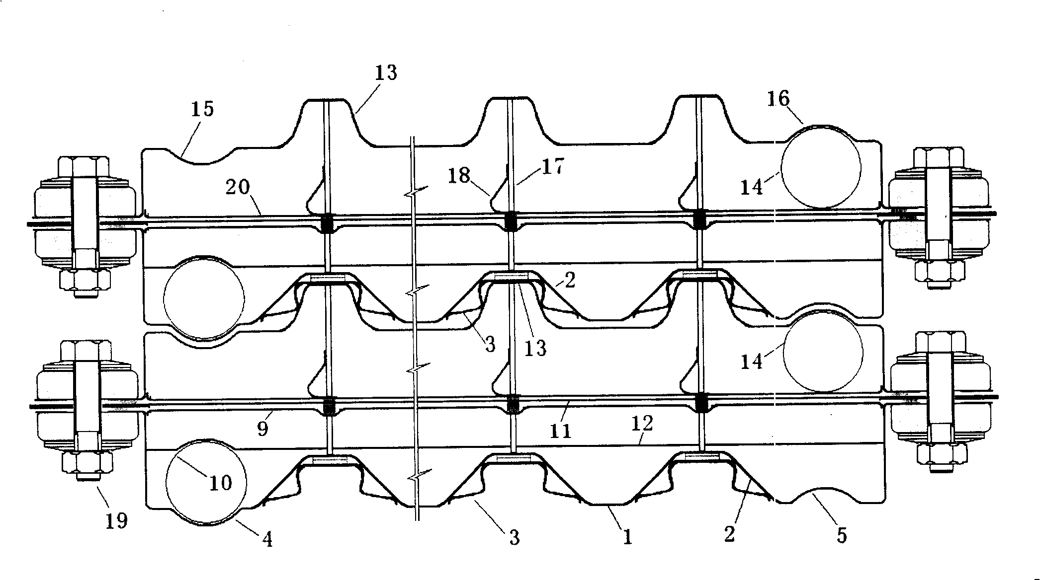
[0083] Figure 7It is another schematic diagram of the horizontal plane of the electrode component with guide grooves and lateral springs on the anode platter of the present invention; its structure and working principle are the same as those in Example 1, except that the anode platter and the cathode platter are set correspondingly The vertical guide groove 2 and the protruding groove 13 are not set in length, but are arranged in sections, and the structure of the conductive spring 3 in the vertical guide groove 2 on the anode platter has not changed, and other structures have no change. Variety.
Embodiment 3
[0085] Figure 8 It is a schematic plane sectional view of an electrode member with guide grooves and lateral springs on the anode platter and a conductive plate at the corresponding position on the cathode platter of the present invention; The spring 3 cooperates with a conductive riser 23, which is characterized in that the compressive force between the conductive pressure and the unit groove is vertical and is not affected by its size. The anode has a recess 25 at the soldering point, on which a protective support pad 24 is provided; other structures are the same as in Embodiment 1.
PUM
 Abstract
Description
Claims
Application Information