Axis external diameter length detection process and device

A detection method and detection device technology, which is applied in the direction of measuring devices, optical devices, instruments, etc., can solve the problems of low efficiency, high work intensity, poor stability, etc., and achieve the effect of simple and convenient operation, slow solution speed and fast speed

Inactive Publication Date: 2008-09-17
SHENZHEN SHENLAN PRECISION MACHINERY
View PDF0 Cites 26 Cited by
  • Summary
  • Abstract
  • Description
  • Claims
  • Application Information

AI Technical Summary

Benefits of technology

This patented system uses both high-quality gratings with precise measurements on long objects like catheters or pipes while still being able to measure their sizes accurately at very short distances (<1 mm). It allows users to quickly set parameters based upon these measurement results without having to manually adjust them during testing. Overall this makes it faster than previous methods that were slower but more accurate compared to current techniques.

Problems solved by technology

This patented technical problem addressed by this patents relates to improving the accuracy and speed at measuring products during their production process without requiring human labor or expensive devices such as scanning electron microscopes (SEM). Current automated systems cannot accurately track small objects due to slow response times caused by insufficient sensitivity and instability. However, there has been developed an improved method called CCD imaging that allows for precise measurements over large areas while reducing complexity issues associated with conventional techniques like SEM.

Method used


Image

  • Axis external diameter length detection process and device
  • Axis external diameter length detection process and device
  • Axis external diameter length detection process and device

Examples


Embodiment Construction

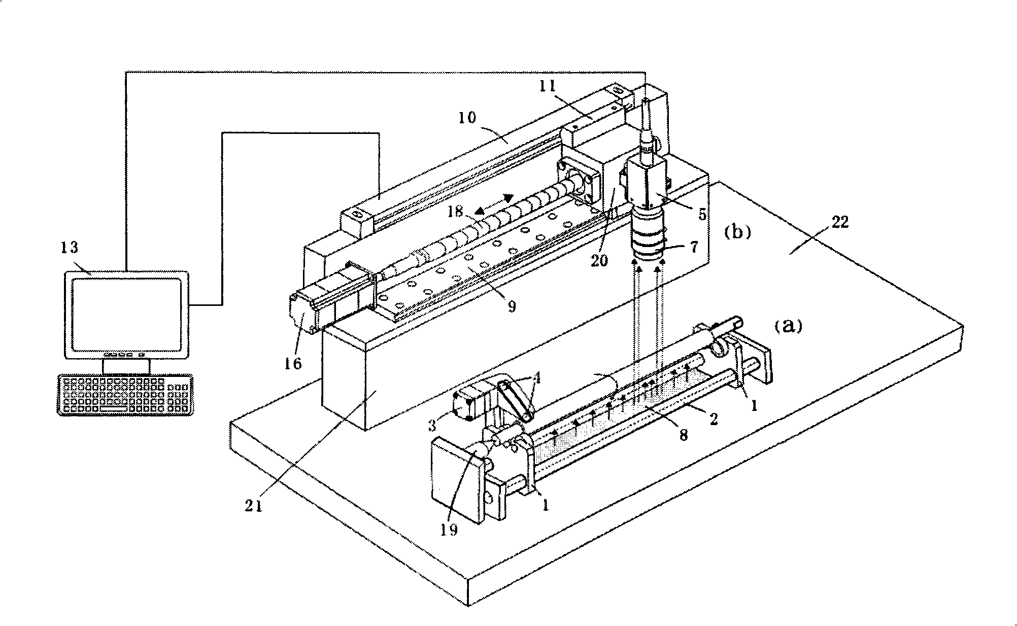
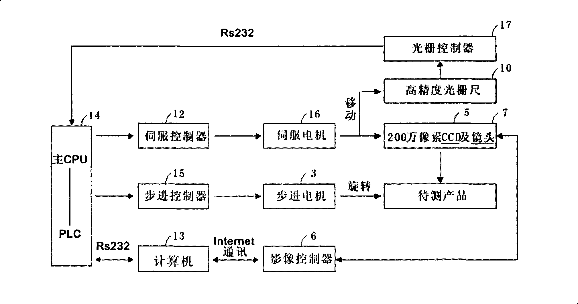
[0024] figure 1 It is a schematic structural diagram of a measuring device according to a specific embodiment of the present invention. figure 1 The middle and bottom are the product receiving platform and the shaft rotation mechanism. The product receiving platform includes two support bases 1 and two guide shafts 2. The two guide shafts 2 are installed horizontally and parallel. The two support bases 1 are installed on the left and right sides of the guide shaft 2 and can move freely along the axial direction of the guide shaft 2. In this way, the distance between the two support seats can be freely adjusted according to the length of the detection shaft. A shaft rotation drive mechanism is arranged behind the left support seat 1. The shaft rotation drive mechanism includes a stepper motor 3 and a pulley 4, which are driven by the stepper motor 3. The rotation of the pulley 4, when the pulley 4 is pressed on the shaft, drives the shaft to rotate radially. When the shaft is ...


PUM


Abstract

The invention discloses an axis outer diameter length examination method and the equipment, the method includes the following steps: (1)after a testing axis is located on a product receiver stage, a CCD phantom system gains image gathering data, the testing object edge position is determined and the edge position data are recorded by that the image is carried on the projection processing, and the corresponding servo position is recorded, then transmitted to a computer; (2) the CCD phantom system is moved to a set location along the axial direction through a level shifting mechanism, and the migration displacement quantity is recorded by a grating ruler equipment then transmitted to the computer, so that the CCD phantom system gains the image gathering data once more, the testing object edge position is determined and the edge position data are recorded by that the image is carried on the projection processing, and the corresponding servo position is recorded, then transmitted to the computer; (3)the step (2) is repeated until the CCD phantom system gains the image of a axis at the final set position; (4)the computer carries on synthesis processing on the image data and the grating data to calculate the value of the axis outer diameter length.

Description


Claims


Application Information

Patent Timeline
Owner SHENZHEN SHENLAN PRECISION MACHINERY
Why Eureka
Try Eureka