A network construction method for single-station territorial laser scanning point cloud

A ground laser scanning and laser scanning technology, applied in the direction of optical devices, instruments, calculations, etc., can solve problems such as difficult to judge the adjacency relationship between points, inconsistent normal directions, and low algorithm efficiency, and achieve the effect of solving calculation efficiency problems

Active Publication Date: 2010-06-09
SHENZHEN D & W SPATIAL INFORMATION TECH
View PDF2 Cites 0 Cited by
  • Summary
  • Abstract
  • Description
  • Claims
  • Application Information

AI Technical Summary

Problems solved by technology

[0004] The direct method is to use the relationship between points to construct a network directly in three-dimensional space, mainly including engraving algorithm, distance function algorithm and surface growth method. The surface of the object, but its biggest problem is that in the case of uneven point density or noise, it is difficult to judge the real adjacency relationship between points, so that it is easy to have surface holes, overlapping patches, and inconsistent normals. In addition, because the direct method involves three-dimensional space analysis, etc., it will occupy more system resources in the case of a large amount of data, and the algorithm efficiency is low
[0005] The indirect method mainly refers to the mapping method. The algorithm of this type of method projects the local adjacent points onto the tangent plane for 2D triangulation, and then stitches them into an overall 3D surface model. This type of method simplifies the complex 3D problem into a 2D problem. It has high efficiency, but its result depends on the selection of the size of the K neighborhood, and the parallel projection of the three-dimensional point set onto the plane can easily lead to errors in the judgment of the adjacency relationship between points

Method used


Image

  • A network construction method for single-station territorial laser scanning point cloud
  • A network construction method for single-station territorial laser scanning point cloud
  • A network construction method for single-station territorial laser scanning point cloud

Examples


Embodiment Construction

[0030] Technical scheme of the present invention comprises the following steps:

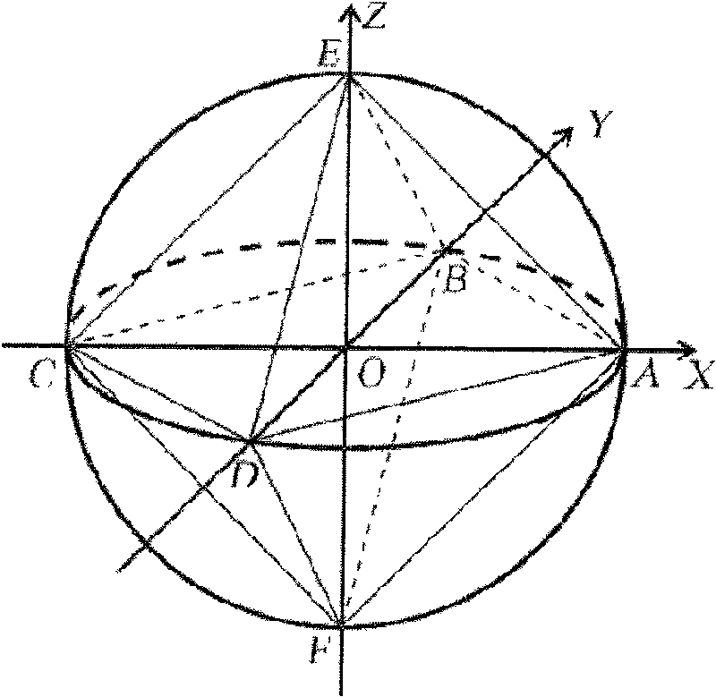
[0031] Step 1, defining a projection sphere, and projecting the single-station laser scanning point cloud to the projection sphere in a central projection manner, the projection sphere is a sphere centered on the center point of the laser emission;

[0032] The scanning method of the ground laser scanner is that the base is fixed, the laser pulse emission direction swings up and down in the vertical direction with the scanning head, and at the same time rotates slowly in the horizontal direction, by recording the direction of the laser pulse and the return time (or phase) difference) to calculate the three-dimensional coordinates of the target surface. When the scanning field of view is large, if all the scanning points are directly projected onto a plane through parallel projection, problems such as point overlap and occlusion will inevitably occur, and the constructed triangulation network cann...


PUM


Abstract

The invention relates to a network configuration method for single-station ground laser scanning point cloud, which includes the following steps: defining a projection sphere and projecting the single-station laser scanning point cloud onto the projection sphere; constructing an initial triangulation; in turn inserting the data points obtained after the projection of point cloud, which includes three steps; searching a triangle containing the data points to be inserted; locally reconstructing a triangulation, that is ,after finding the triangle containing the data points to be inserted ,connecting the points with the three sides of the triangle to form three new triangles; carrying out sphere LOP local optimization for the new triangulation obtained by local reconstruction; deleting six intersecting points constructing the initial triangulation to obtain a Delaunay triangulation of the projection-point sphere; projecting back the data points in the Delaunay triangulation of the projection-point sphere to the initial positions to obtain a target triangulation of the single-station laser scanning point cloud. The technology scheme provided by the invention, which can greatly improvethe efficiency of reconstructing object surface with ground laser scanning technique, is of great significance in reverse engineering technology.

Description

technical field [0001] The invention belongs to the technical field of reverse engineering, and in particular relates to a network construction method for single-station ground laser scanning point clouds when ground laser scanning technology is used for object surface reconstruction. Background technique [0002] The terrestrial laser scanning system adopts the non-contact active measurement method to directly acquire high-precision three-dimensional data. It has the characteristics of fast scanning speed, strong real-time performance, high precision, strong initiative, and full digital features. It is an efficient data acquisition mode. It has a wide range of applications in engineering technology and other fields. Inside the ground laser scanner, through two synchronous mirrors rotating rapidly and orderly, the narrow-beam laser pulses emitted by the laser pulse emitter are scanned across the measured area in sequence, and each laser pulse is measured from the point where...

Claims


Application Information

Patent Timeline
Patent Type & Authority Patents(China)
IPC IPC(8): G06T17/30G01B11/00
Inventor 黄先锋张帆
Owner SHENZHEN D & W SPATIAL INFORMATION TECH
Why Eureka
Try Eureka