
Capacitor micro microphone chip

A microphone and capacitive technology, which is applied in the field of microphone chips, can solve the problems of low process yield, large variation in finished product quality, and difficult control of the process, and achieve the effects of reducing volume, improving yield, and reducing the cost of consumables

Inactive Publication Date: 2008-09-17
TAIWAN CAROL ELECTRONICS
View PDF0 Cites 28 Cited by
  • Summary
  • Abstract
  • Description
  • Claims
  • Application Information

AI Technical Summary

Problems solved by technology

[0004] No matter the microphone chip packaged in the single-chip or double-chip condenser microphone, the common disadvantage is that bulk etching must be carried out in the manufacturing process to form the necessary "chip" for the condenser microphone. diaphragm (diaphragm)” and “air gap (air gap)” and other structures; and when the bulk etching process is required, the more parts to be etched, the longer the etching time required, and the more difficult the process is to control , the quality of the finished product will vary greatly, and the process yield cannot be improved; in addition, when the wafer is cut, the structure of the formed microphone chip will be damaged, resulting in a decrease in the overall process yield

Method used


Image

  • Capacitor micro microphone chip
  • Capacitor micro microphone chip
  • Capacitor micro microphone chip

Examples


Embodiment Construction

[0018] Below in conjunction with accompanying drawing and embodiment the present invention is described in detail:

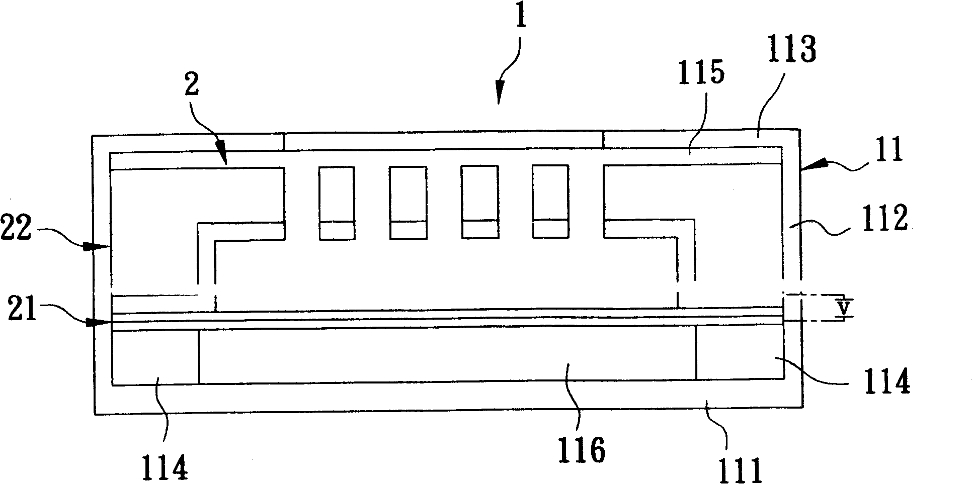
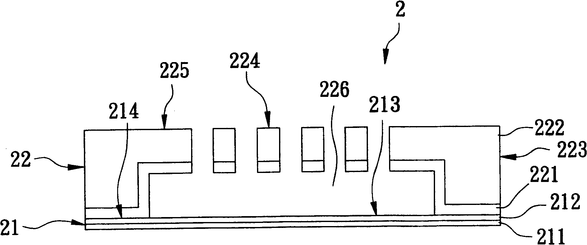
[0019] refer to figure 1 , figure 2 , a first preferred embodiment of the microphone chip of the capacitive miniature microphone of the present invention is that it can cooperate with a housing base 11 to be packaged as figure 1 The capacitive miniature microphone 1 shown is used to sense external sound energy changes.

[0020] The shell seat 1 includes a bottom wall 111, a peripheral wall 112 extending upward from the peripheral edge of the bottom wall 111, a top wall 113 connected to the top edge of the peripheral wall 112 and capable of penetrating sound energy, and a The packaging block 114 on the 111 , the bottom wall 111 , the surrounding wall 112 , and the top wall 113 jointly define a packaging space 115 for the microphone chip 2 to be accommodated.

[0021] The microphone chip 2 is manufactured using semiconductor manufacturing process, MEMS technol...


PUM


Abstract

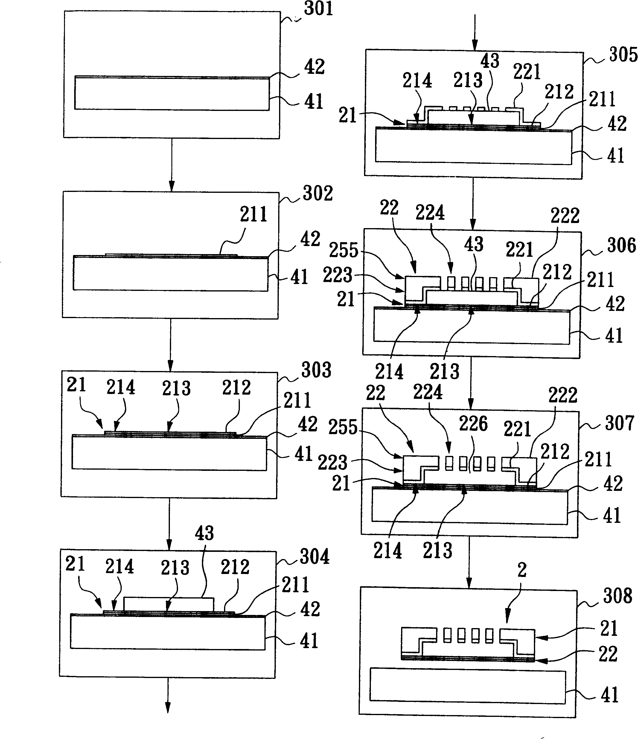
The invention discloses a microphone chip of a capacitor micro-microphone, the capacitor micro-microphone is obtained by orderly defining and forming a disengaging layer, a first electrode layer, a diaphragm layer and a sacrifice layer on a substrate by a semiconductor manufacturing process and a micro-electromechanics technology, then continuing defining a second electrode layer and a strengthening layer, etching and caverning the sacrifice layer through using sound hole images formed correspondingly to the second electrode layer and the strengthening layer to form air gaps, forming the capacitor micro-microphone connected with a substrate, and finally etching and removing the disengaging layer by a disengaging technology so that the capacitor micro-microphone is disengaged from the substrate. Because the method adopts the semiconductor manufacturing process and the micro-electromechanics technology, the capacitor micro-microphone is manufactured without a cutting process, the volume of the capacitor micro-microphone can be accurately reduced, the good rate of the manufacturing process is increased, and the substrate can be reclaimed and reused so as to reduce material cost.

Description

technical field [0001] The invention relates to a chip, in particular to a microphone chip packaged into a miniature microphone. Background technique [0002] Generally, miniature microphones can be divided into three types: piezoelectric, piezoresistive, and capacitive. Among them, the capacitive miniature microphone has the advantages of high sensitivity, low noise, low distortion, and low power consumption. , And become the mainstream of the current development of miniature microphones. [0003] However, the microphone chip packaged into a capacitive miniature microphone can be simply divided into a single-chip type that consists of a single substrate through multiple semiconductor manufacturing processes, such as lithography, etching, evaporation (sputtering) plating..., and then cutting (sawing). , and the two-chip type that consists of two separately formed chips and then bonded into one. [0004] No matter the microphone chip packaged in a single-chip or a two-chip ...

Claims


Application Information

Patent Timeline
Patent Type & Authority Applications(China)
IPC IPC(8): H04R19/01H04R19/04H04R7/00
Inventor 洪瑞华张昭智蔡圳益胡辜昱蒋宇宁
Owner TAIWAN CAROL ELECTRONICS
Learn More