
Method for setting bracing column in underground cavity

A technology for underground caverns and support columns, applied in the field of support columns, can solve the problems of the gap between the grouting surface and the cave roof, the inability to fill the space, and the increase of engineering costs, so as to avoid invalid grouting, save materials, protect The effect of ecological environment

Inactive Publication Date: 2008-09-24
NORTHWEST RES INST CO LTD OF C R E C
View PDF0 Cites 23 Cited by
  • Summary
  • Abstract
  • Description
  • Claims
  • Application Information

AI Technical Summary

Problems solved by technology

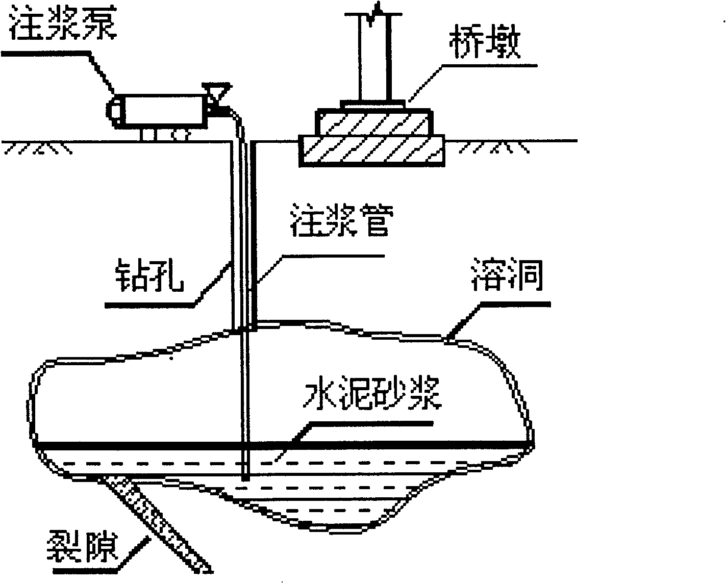
But this will produce a lot of invalid grouting, especially when the underground caverns are connected with cracks, the amount of invalid grouting will be larger, resulting in increased engineering costs
For underground karst caves, when the underground karst caves are very large or connected with underground underground rivers, they may even become "bottomless pits". Even if the amount of grouting is large, it may never be able to fill its space; After decades or even hundreds of years of mining in some mining areas, it is impossible to backfill the goaf in a short period of time. Even if the backfill is full, due to the shrinkage of the cement mortar, there will be a gap between the grouting surface and the cave roof. possible re-deformation
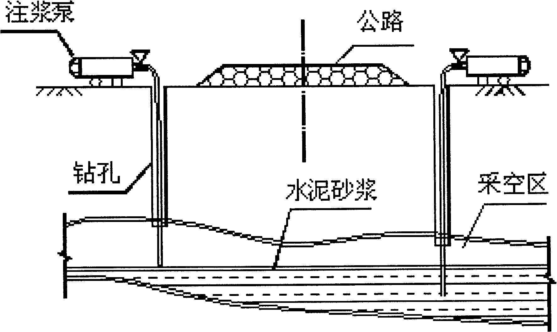
Especially for belt-shaped projects such as highways, railways, canals and airports, it is only necessary to prevent subsidence within the scope of the project. It is necessary to control the scope of reinforcement and reduce investment. The current method is difficult to achieve

Method used


Image

  • Method for setting bracing column in underground cavity
  • Method for setting bracing column in underground cavity
  • Method for setting bracing column in underground cavity

Examples


Embodiment Construction

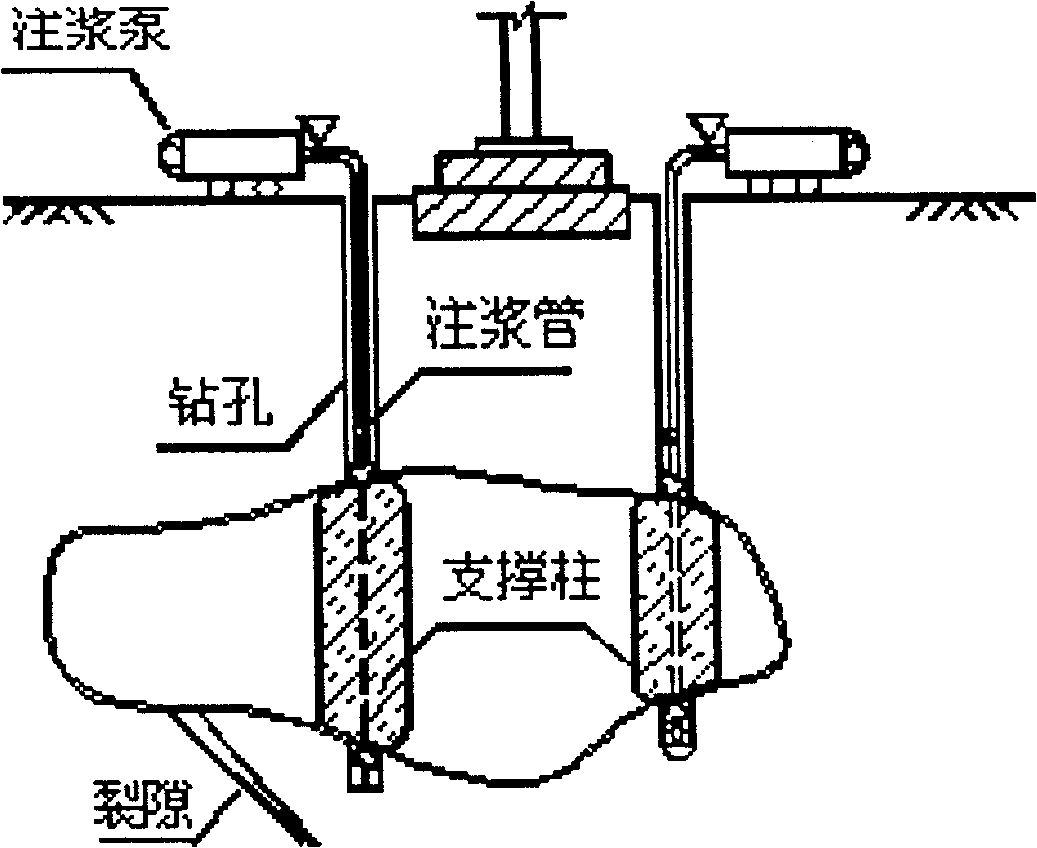
[0020] attached Figure 5 It is a specific embodiment of the present invention. Among them: 1-drilling; 2-the rope binding the lower opening of the bag or the upper opening of the bag; 3-the bag for filling cement mortar; 4-steel pipe; 5-the hole on the steel pipe wall for the outflow of cement mortar; 6 - Inner pull rope; 7 - Mortar; 8 - Bottom plug located in the lower end of the steel pipe for blocking the lower nozzle; 9 - Grouting pipe.

[0021] The implementation process of the present invention is as follows:

[0022] Use a drilling rig on the ground to drill hole 1 into the underground cavity. The diameter of hole 1 can be 9 to 13 cm. You can also drill a hole with a larger diameter according to the design requirements. After drilling through the top of the hole, continue drilling to the bottom of the cavity. , until the drilling reaches 40-60 cm below the bottom of the cavern. Get the steel pipe 4 whose outer diameter is smaller than the borehole diameter and whose...


PUM


Abstract

The invention relates to a method for arranging a supporting column used for preventing the ground from collapsing and deforming in an underground cavern (cave, laneway). The invention has broad applications in the constructions of roads, railways, airdromes and water conservancy projects which have underground caves or goaf roadways and can also be applied to the field of environment resuming and governing of a surface collapse area or a mine goaf area. The method of the invention includes: using a drill to drill a bore from the ground to the underground until entering into 40 to 60cm under the bottom surface of the cavern, then inserting a steel pipe the outside of which is coated by a bag into the bottom part of the bore, then inserting a grouting pipe into the bottom part of the steel pipe, pouring cement slurry into the pipe by using a grouting pump through a grouting pipe; a supporting body is formed after the bag is fully filled and solidified. A plurality of supporting columns can also be arranged in the cavern according to the method to form a supporting column group or a curtain wall formed by the supporting columns.

Description

technical field [0001] The invention relates to a method for arranging support columns for preventing surface subsidence and deformation in underground caverns (caves, roadways). The invention will be widely used in the construction of highways, railways, airports and water conservancy projects with caves or goafs underneath, and can also be used in the fields of environment restoration and treatment of karst subsidence areas and mine goafs. Background technique [0002] In limestone karst areas or in coal mining and mining areas, underground caves often collapse, causing large-scale subsidence and deformation of the surface. When constructing highways, railways, water conservancy channels, airport runways or other engineering constructions in these areas, the surface subsidence and deformation caused by underground caves seriously threaten the safety of the superstructure, and even cause large-scale damage to the above-ground buildings. Not only that, the collapse of under...

Claims


Application Information

Patent Timeline
IPC IPC(8): E02D27/34
Inventor 王桢
Owner NORTHWEST RES INST CO LTD OF C R E C
Learn More