Air-fuel ratio control system of combustion heating furnace

An air-fuel ratio and control system technology, which is applied in the combustion method, combustion control, and fuel supply adjustment, etc., can solve the problems of less usage, uneven temperature distribution, and uneven firing quality, and achieves the goal of preventing unevenness. Qi effect

Active Publication Date: 2008-09-24
NGK INSULATORS LTD
View PDF1 Cites 26 Cited by
  • Summary
  • Abstract
  • Description
  • Claims
  • Application Information

AI Technical Summary

Problems solved by technology

As a result, in the low temperature range, the temperature distribution in the furnace tends to become non-uniform, and there is also a problem that the firing quality of the product varies.
In addition, as shown in Patent Document 1...

Method used


Image

  • Air-fuel ratio control system of combustion heating furnace
  • Air-fuel ratio control system of combustion heating furnace
  • Air-fuel ratio control system of combustion heating furnace

Examples


Embodiment Construction

[0033] Embodiments of the present invention will be described below.

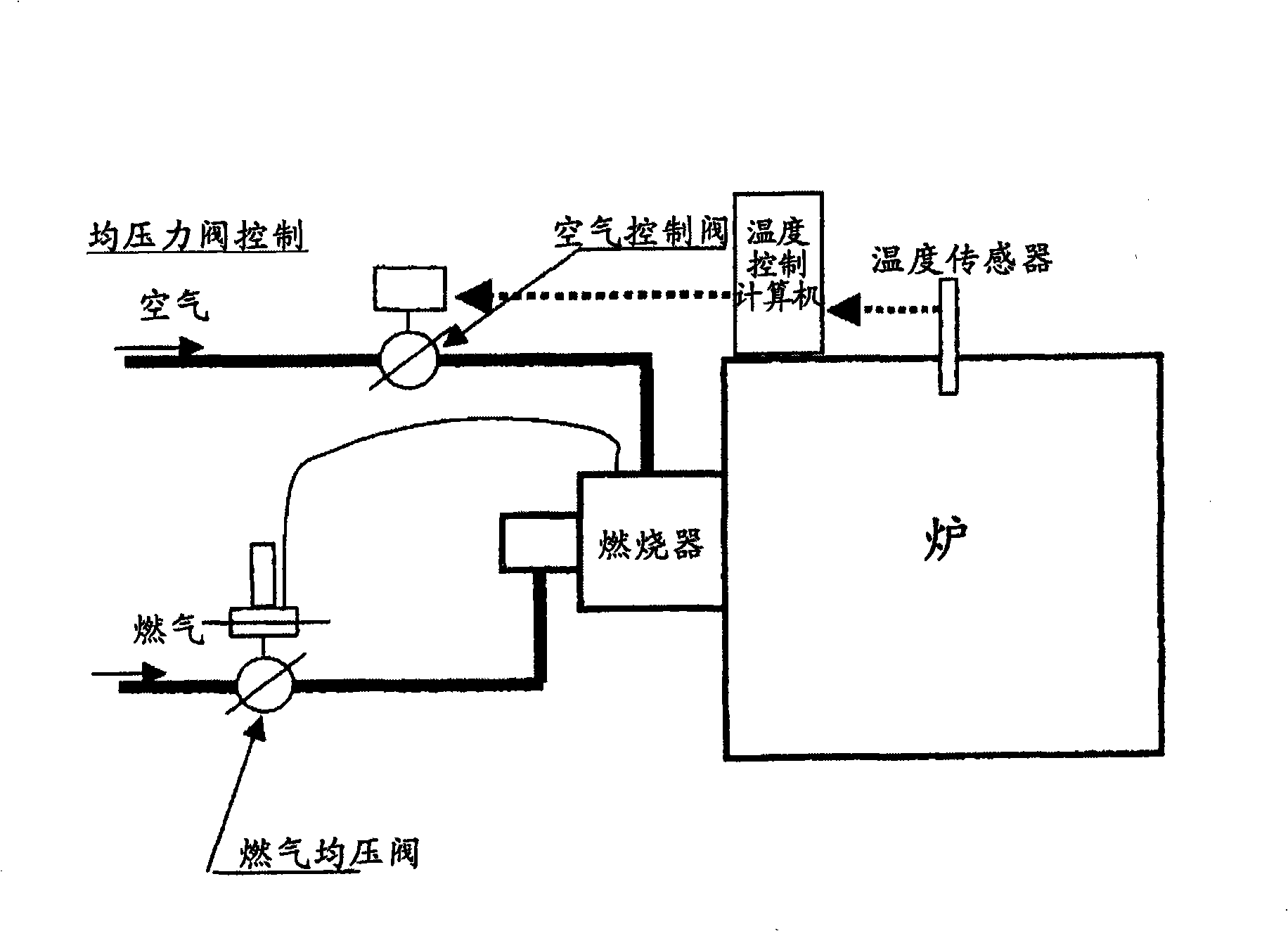
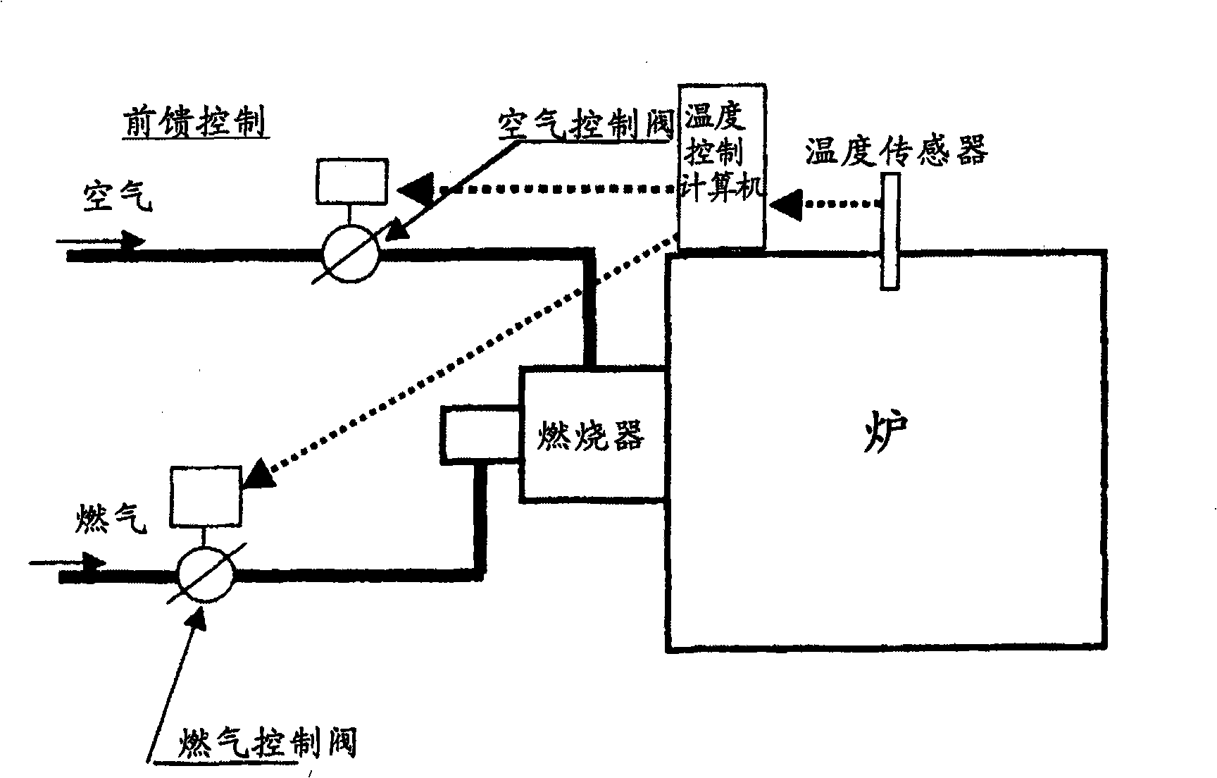
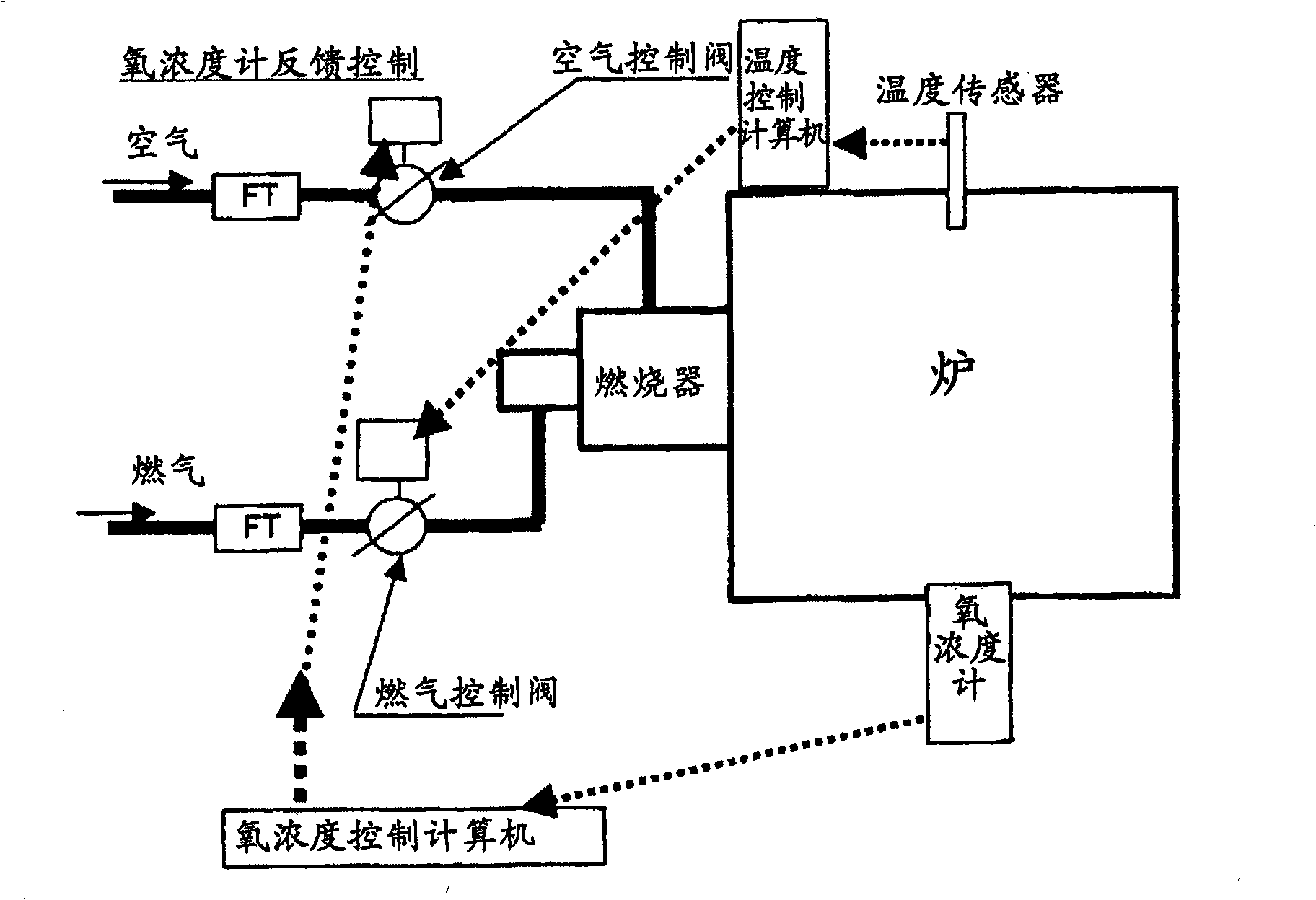
[0034] exist Figure 4 Among them, 1 is a furnace body of a combustion heating furnace used for heating and firing of various kiln products and ceramic products, and 2 is a burner installed in the furnace body 1 . In this figure, only one burner 2 is illustrated for explanation, but it goes without saying that a plurality of burners 2 are actually installed. Burner 2 is a gas burner, 3 is a gas supply pipe, and 4 is an air supply pipe. The furnace body 1 of this embodiment is a batch furnace, preferably a shuttle kiln.

[0035] A gas flow meter 5 and a gas flow control valve 6 are provided in the gas supply pipe 3 , and an air flow meter 7 and an air flow control valve 8 are provided in the air supply pipe 4 . In addition, a temperature sensor 9 is installed in the furnace body 1 .

[0036] 10 is a computer for temperature control. This temperature control computer 10 has a temperature control function...


PUM


Abstract

The invention provides an air fuel ratio control system of a burning heating furnace capable of controlling burning widely from oxidation burning to restoring burning and of determining oxygen concentration simply lacking of operators with technical knowledge. The system includes a burner (2) arranged in the burning heating furnace, a fuel supply pipe (3) supplying fuel gas to the burner (2), an air supply pipe (4) supplying air for burn to the burner (2) and a temperature control computer (10). The temperature control computer (10) pre-remembers a first formula (burning air amount=fuel gas flow*theoretical air amount*air fuel ratio) and a second formula (air fuel ratio=20.6/20.6-oxygen concentration) and automatically controls burning air amount according to the gas flow based on the formula when inputting the oxygen concentration.

Description

technical field [0001] The present invention relates to the air-fuel ratio control system of the combustion heating furnace used in the heating and firing of various kiln products and ceramic products, especially the air-fuel ratio control system of the combustion heating furnace capable of reduction firing. Background technique [0002] The above-mentioned combustion heating furnace is provided with a plurality of gas burners as heating sources, and a desired temperature profile is obtained by controlling the gas flow rate and the air flow rate supplied to the gas burners. The operation control of such a combustion heating furnace was performed manually in the past, but due to the increase of products requiring strict firing conditions and the desire for unmanned operation at night, etc., in recent years, automatic control by a computer for temperature control Control is becoming more common. In addition, when firing products that require reduction firing, the temperature ...

Claims


Application Information

Patent Timeline
IPC IPC(8): F23N1/02
Inventor 中浴运雄
Owner NGK INSULATORS LTD
Why Eureka
Try Eureka