Shuttle type kiln

A shuttle kiln and a shuttle-type technology are applied in the field of shuttle kilns, which can solve the problems of increased furnace construction cost, complex furnace body structure, low temperature, etc., and achieves restraining energy consumption, low furnace construction cost, and excellent energy saving effect. Effect

Inactive Publication Date: 2008-09-24
NGK INSULATORS LTD
View PDF1 Cites 4 Cited by
  • Summary
  • Abstract
  • Description
  • Claims
  • Application Information

AI Technical Summary

Problems solved by technology

However, since such a shuttle kiln is generally equipped with a forced exhaust device and a complicated flue structure connected thereto in order to form a desired gas flow in the furnace, the furnace body becomes a large and expensive equipment, so it is not necessary to Suitable for settings in SMEs or developing countries
[0004] For example, in the shuttle kiln of Patent Document 1, exhaust passages are respectively formed at the bottom of the two side walls on the long side of the furnace, and the front ends of these exhaust passages are connected to the chimney outside the furnace through the

Method used


Image

  • Shuttle type kiln
  • Shuttle type kiln
  • Shuttle type kiln

Examples


Embodiment Construction

[0019] Hereinafter, preferred embodiments of the present invention will be shown with reference to the drawings.

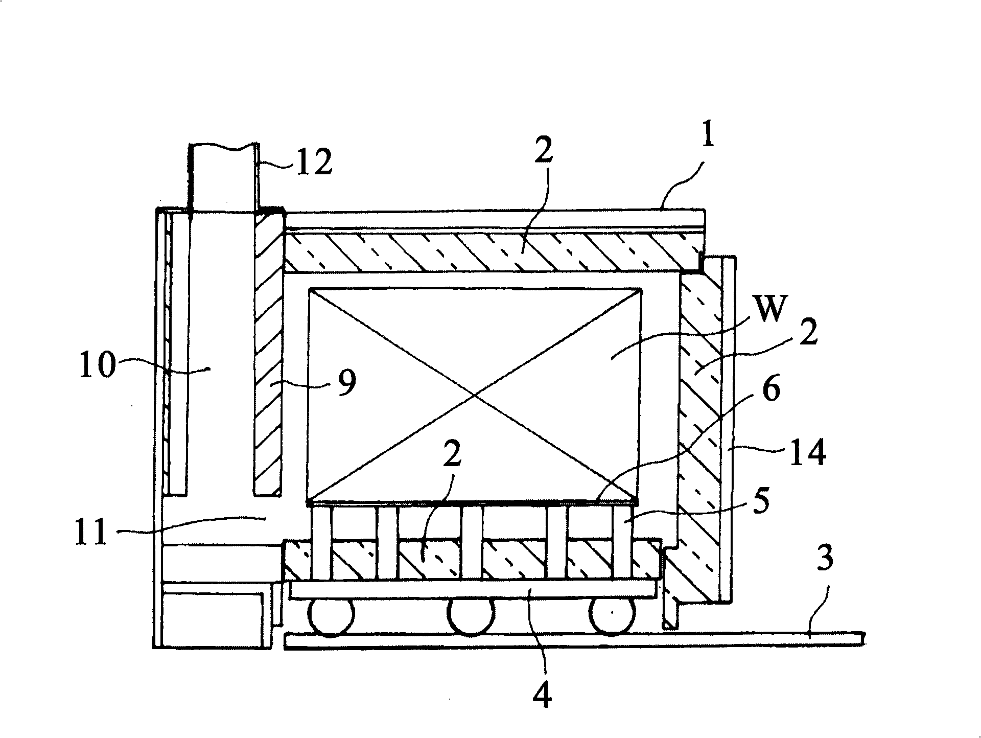
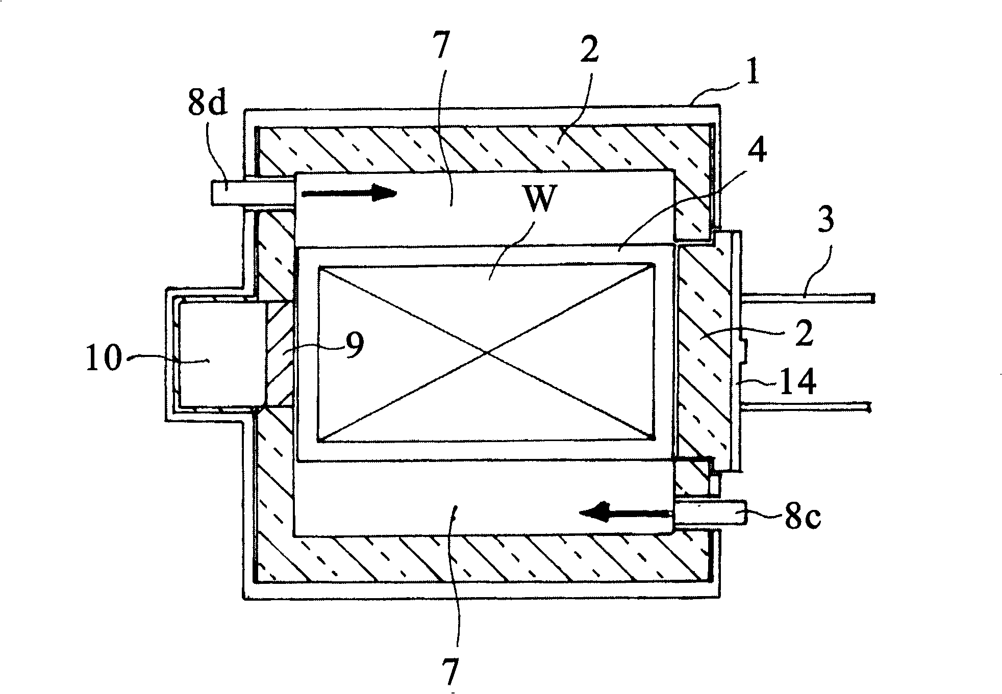
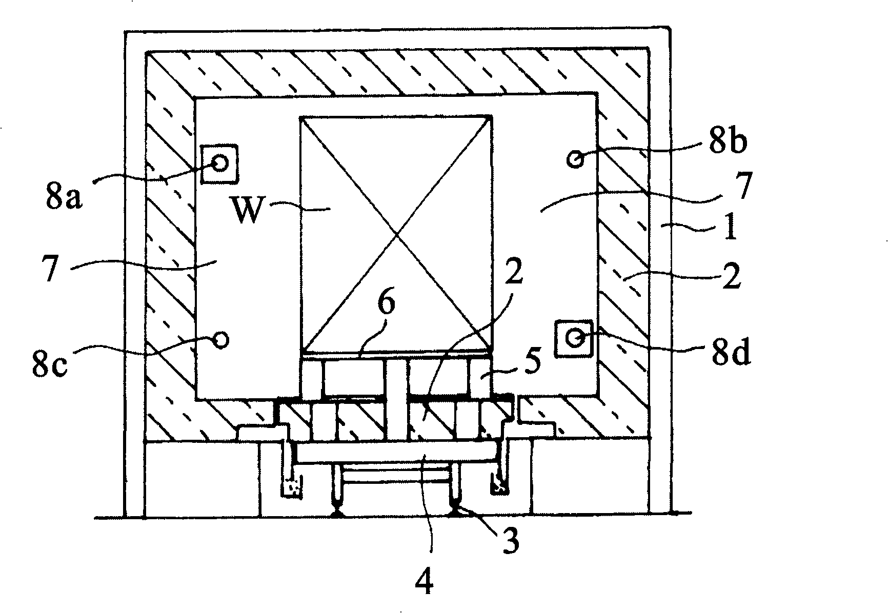
[0020] Figure 1 ~ Figure 3 It is a sectional view of the shuttle kiln of this invention, 1 is a furnace body which consists of ceramic fiber 2 with a furnace wall and a furnace roof, and it has a substantially rectangular parallelepiped shape as shown in a figure. The inner volume of the furnace should preferably be 8m 3 Below, therefore, the maximum furnace width and furnace height are only about 2 m.

[0021] A track 3 extending to the outside of the furnace is laid on the floor in the furnace so that the kiln car 4 can enter and exit. The upper part of the kiln car 4 is supported by ceramic pillars 5 to support the shelf group 6, so that gas flow passages are provided between each other and products W to be fired can be loaded. In addition, the roof of the kiln car 4 is also made of ceramic fiber 2, so that the heat capacity of the furnace body 1 and the ki...


PUM


Abstract

The invention provides a shuttle kiln for ceramics firing with good energy-saving performance, simple kiln structure and low manufacturing cost, which is not easy to produce non-uniformity of ceramics firing caused by kiln placing position. The invention is composed of a kiln wall and a kiln roof made from ceramic fiber (2), which is a shuttle kiln having a kiln car (4) inside. A flue (10) forms with a kiln wall by protruding a central part of a rear wall of the kiln body (1) outwards, and an exhaust vent forms at the lower part thereof from a kiln chamber to the flue (10). A plurality of section of a burner (8) is configured oppositely fore and after at fore and after positions of left and right kiln walls, in the manner of forming opposite swirling flow of fire in each horizontal plane up and down. Compared with current product, the invention is capable of reducing the cost greatly.

Description

technical field [0001] The present invention relates to a shuttle kiln for firing ceramics. Background technique [0002] The shuttle kiln makes the kiln car go back and forth between the inside and outside of the furnace. The product is loaded on the kiln car outside the furnace and stored in the furnace as it is for firing. After the firing is completed, the kiln car is pulled A batch-type firing furnace that is taken out of the furnace. Since this type of furnace is different from a continuous furnace, the body of furnace itself repeatedly heats up and cools down in a certain cycle, so from the point of view of energy saving, it is advisable to have a small heat capacity of the body of furnace. No. 180565 bulletin), the fiber-lined furnace that has made furnace wall and furnace top by ceramic fiber is widely used. [0003] In addition, since the shuttle kiln has no product movement during firing, the temperature distribution in the furnace is directly related to the une...

Claims


Application Information

Patent Timeline
IPC IPC(8): F27B3/00F27B3/10F27B3/12F27B3/20F27D1/00F27D1/02F27D1/18F27D3/12
Inventor 中浴运雄
Owner NGK INSULATORS LTD
Why Eureka
Try Eureka