
Channel estimation method and device based on array antenna

An array antenna and channel estimation technology, which is applied in the field of channel estimation based on array antennas, can solve the problems of ineffective use of array antenna correlation, enlargement of noise power, loss of signal-to-noise ratio, etc., so as to improve position estimation accuracy and signal-to-noise ratio ratio, the effect of reducing the bit error rate

Inactive Publication Date: 2010-04-14
ZTE CORP
View PDF3 Cites 4 Cited by
  • Summary
  • Abstract
  • Description
  • Claims
  • Application Information

AI Technical Summary

Problems solved by technology

However, the performance of Steiner estimation is affected by the additive noise at the receiving end. Compared with the ideal channel response, the obtained channel response contains noise components, that is, the channel estimation error; at the same time, it will also expand the noise power, resulting in signal noise at the output There is a certain amount of loss at the input terminal than the relative
[0004] To solve this problem, in the document "Improvement of low-cost channel estimation method in TD-SCDMA system" (Kang Shaoli, Qiu Zhengding, Li Shihe, Journal of Communications, Vol.23 No.10, 2002, 108-113.), proposed A noise reduction method for threshold detection. This method has a small amount of calculation and can improve the performance of the system. However, in the application of array antennas, the correlation between the elements of the array antenna cannot be effectively used. , there is still a lot of room for improvement in the performance of channel estimation

Method used


Image

  • Channel estimation method and device based on array antenna
  • Channel estimation method and device based on array antenna
  • Channel estimation method and device based on array antenna

Examples


Embodiment Construction

[0020] Hereinafter, each preferred embodiment of the present invention will be described in detail with reference to the accompanying drawings.

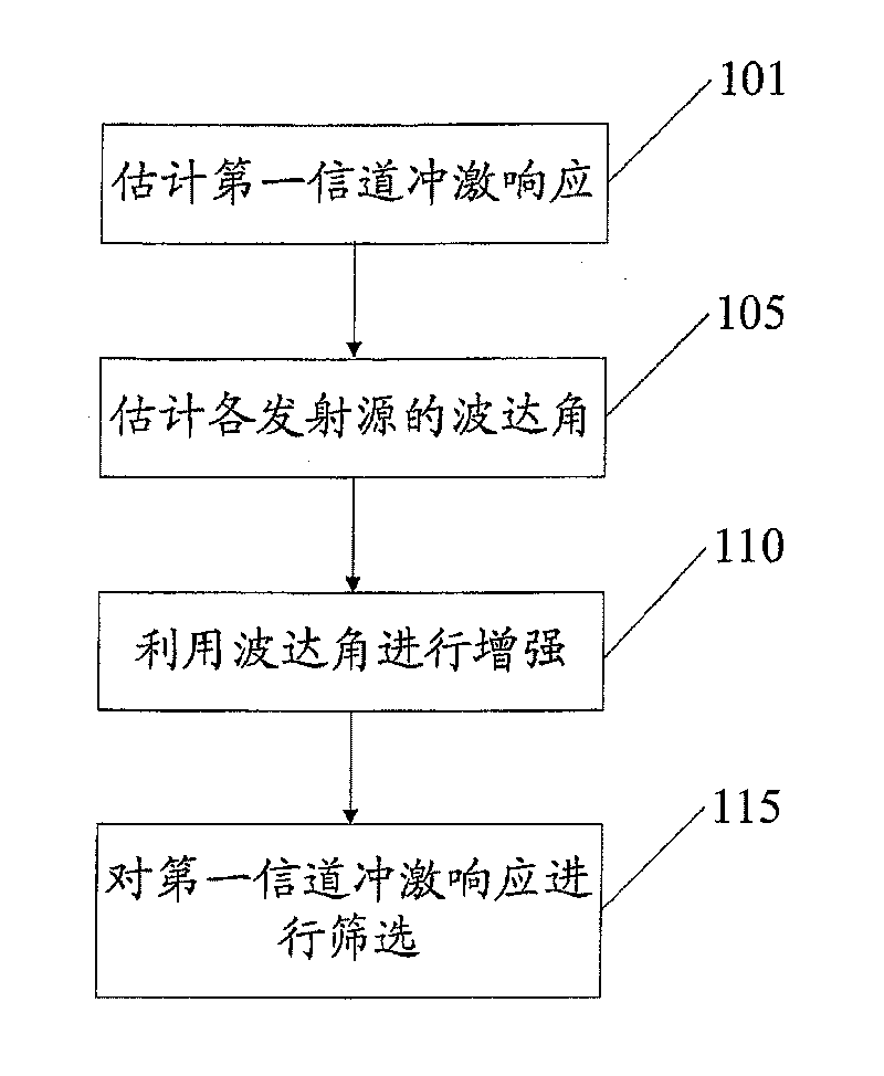
[0021] figure 1 It is a flowchart of a channel estimation method based on an array antenna according to an embodiment of the present invention. Such as figure 1 As shown, in step 101, the first channel impulse response is estimated according to the received signal and training sequence of the array antenna Wherein, the received signals of the array antenna are radio frequency signals from multiple transmission sources, and the first channel impulse response includes the channel impulse response of each of the multiple transmission sources.

[0022] Specifically, in this step, taking TD-SCDMA as an example, first separate the part e corresponding to the training sequence from the received signal mid , Which can be expressed as

[0023] e mid =Gh+n (1)

[0024] Among them, the G matrix is ​​a cyclic right shift matrix composed of a basic Mi...


PUM


Abstract

A business form including a wristband is provided with a print area forming a badge, the badge having a length less than and a width greater than a width of either of two straps used to attach the wristband to the wrist, the badge thus having a greater print area to improve the readability of the indicia displayed therein. A business form including a wristband has a bulged rectangularly shaped print area to allow information to be printed transversely across the print area to improve readability of the indicia displayed in the print area. Thus, the bulged rectangularly shaped print area can accommodate one or both of bar codes printed thereon in ladder as well as picket fence fashion.; A security seal is disclosed which comprises a small, adhesive coated patch of laminate for sealing the joinder of the wristband ends and which has points of weakness such as X's die cut therein so that it separates or destructs upon removal to provide an indication of tampering with the wristband. Alsodisclosed is an embodiment of the wristband form that is imprinted with identifying indicia for collecting, tracking and administering a patient's blood collection and blood product compatibility.

Description

Technical field [0001] The present invention relates to mobile communication technology, in particular to an array antenna-based channel estimation technology. Background technique [0002] Many key technologies are involved in the mobile communication system, such as channel estimation technology, joint detection technology, smart antenna technology, etc. However, both the joint detection technology and the smart antenna technology are based on channel estimation, and the effect of channel estimation has an extremely important influence on the performance of joint detection. The multipath propagation of signals in the wireless mobile environment poses a severe challenge to channel estimation. How to obtain accurate channel estimation under harsh channel propagation conditions has become the key to affecting the quality of mobile communications. Therefore, reducing the error of channel estimation, that is, reducing or eliminating the noise in the channel response, is an urgent p...

Claims


Application Information

Patent Timeline
Patent Type & Authority Patents(China)
IPC IPC(8): H04B1/38H01Q21/00
CPCH04L25/0212H04L27/2647H04L25/0232H04B7/086
Inventor 李萍刘斌肖炼斌罗志年
Owner ZTE CORP
Learn More