Check patentability & draft patents in minutes with Patsnap Eureka AI!

Printing substrate processing machine

A processing machine and printing-based technology, which is applied to metal processing machinery parts, metal processing, metal processing equipment, etc., can solve the problems of complex worktable rigidity and other problems, and achieve the effects of simple structure, deformation prevention, and improved processing accuracy

Inactive Publication Date: 2008-10-01
HITACHI SEIKO LTD
View PDF1 Cites 3 Cited by
  • Summary
  • Abstract
  • Description
  • Claims
  • Application Information

AI Technical Summary

Problems solved by technology

[0010] However, the device of the printing substrate processing machine in Patent Document 1 is relatively complicated, and the rigidity of the workbench needs to be considered

Method used


Image

  • Printing substrate processing machine
  • Printing substrate processing machine
  • Printing substrate processing machine

Examples


Embodiment Construction

[0027] Hereinafter, a printed substrate processing machine according to an embodiment of the present invention will be described with reference to the drawings.

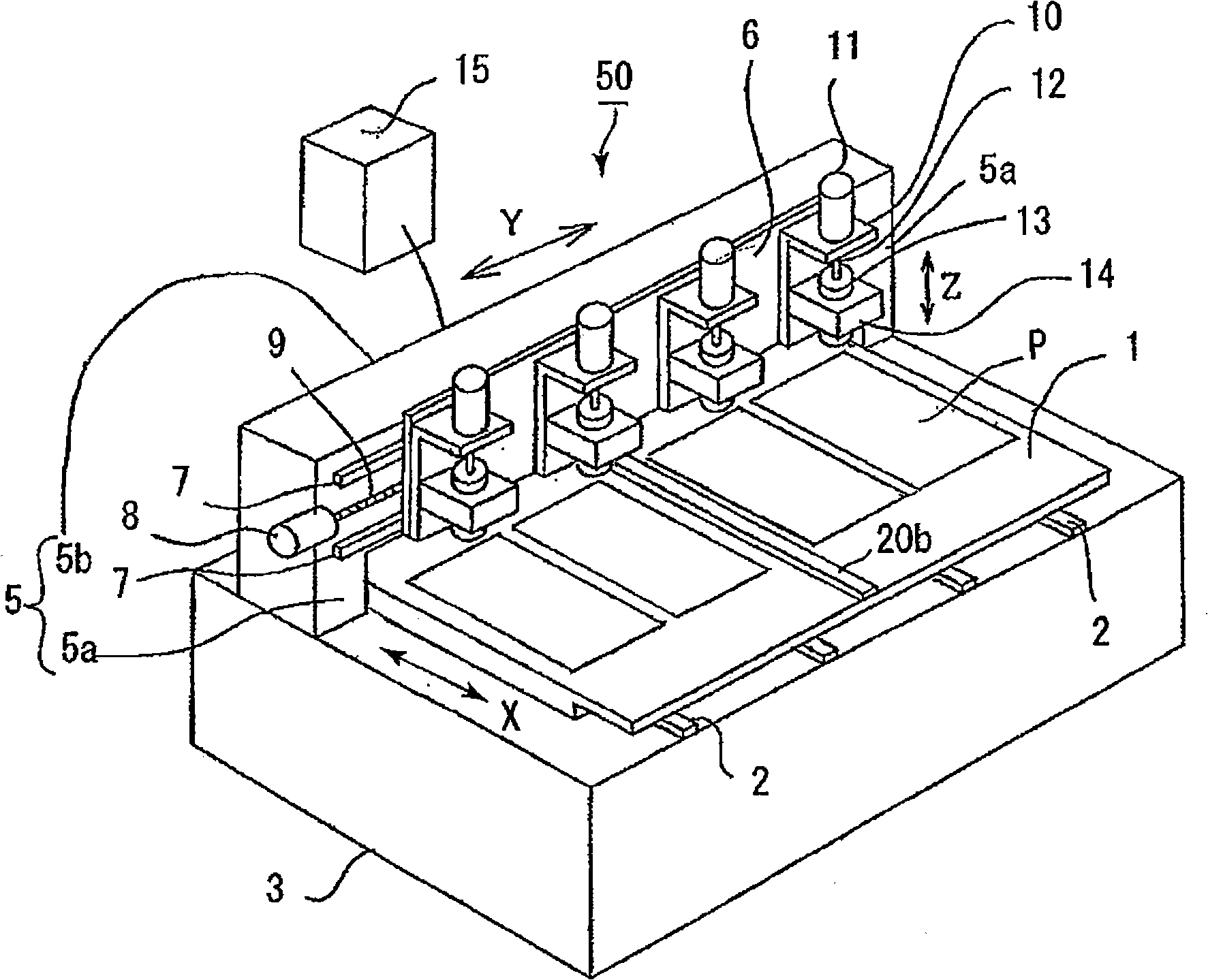
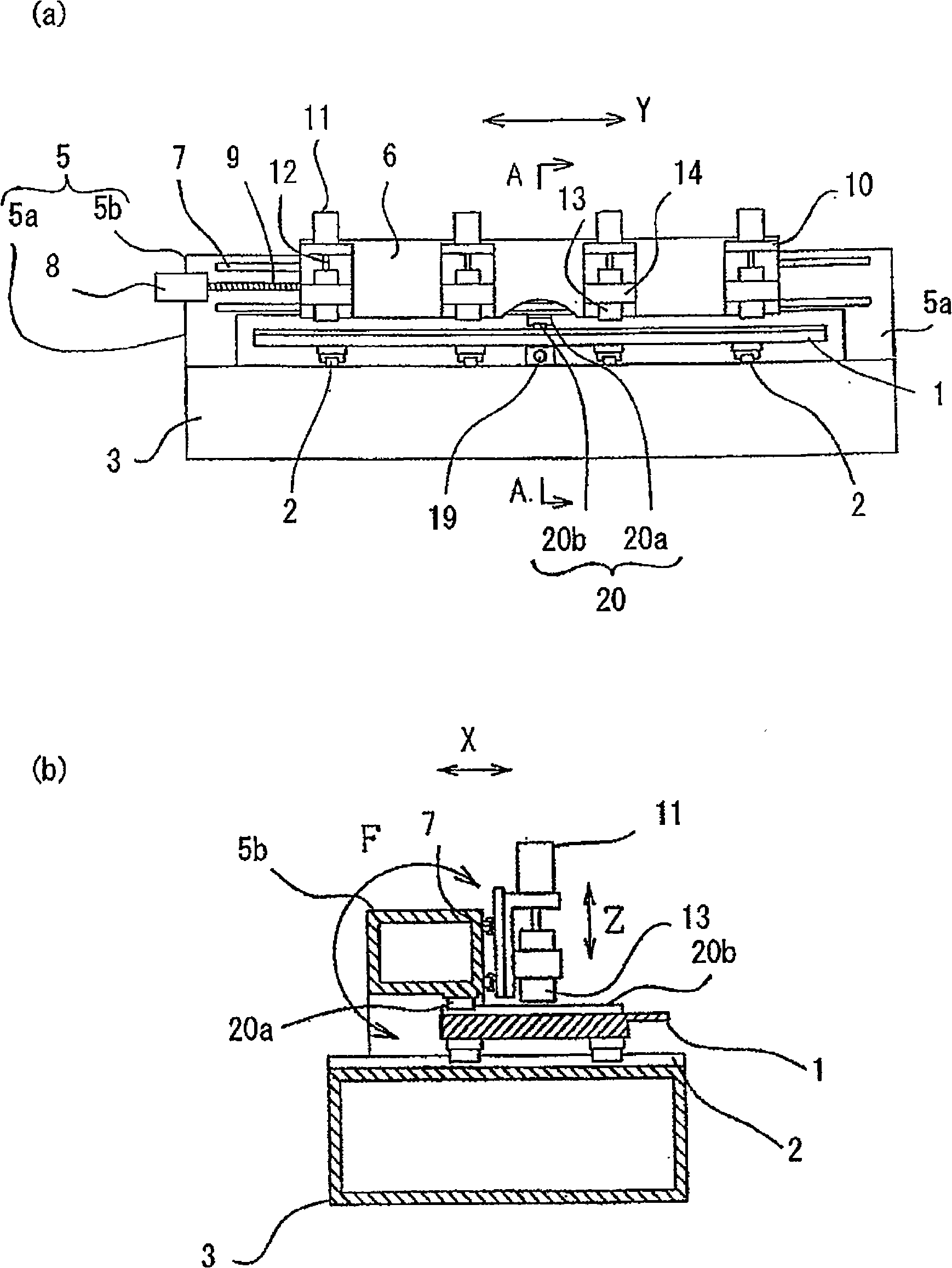
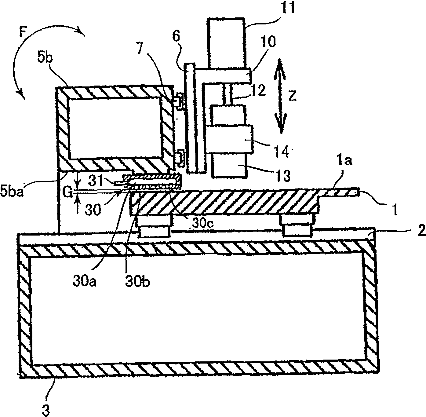
[0028] figure 1 It is an external perspective view of the printed circuit board processing machine in the embodiment of the present invention. figure 2 (a) is figure 1 Front view of the printed substrate processing machine. figure 2 (b) is figure 2 (a) A-A arrow sectional view.

[0029] The printed substrate processing machine 50 drills holes in the printed substrate P. As shown in FIG. The table 1 is supported on the linear guide device 2, and is passed through a drive motor and a feed screw 19 (not shown). figure 2 ) on the base 3 along the arrow X direction. Four (not limited to four) printing substrates P are fixed on the table (X table) 1 .

[0030] The pillar 5 is constituted by a pair of leg parts 5a and a beam part 5b connecting the pair of leg parts 5a, is formed in a gate shape, straddles the t...


PUM


Abstract

The invention provides a print substrate processing machine which reduces twist of a stanchion with a simple structure so as to improve processing precision. With respect to the invention, the print substrate processing machine (50) includes: a pedestal (3), a working table (1) which supports the print substrate and is movable on the pedestal (3), a door stanchion (5) which steps over the working table (1) and is provided on the pedestal (3), and a beam part (5b) provided at the door stanchion (5) and a main shaft unit processing the print substrate; in addition, a straight line guide device (20) of the beam part (5b) is provided between the working table (1) and the beam part (5b) of the stanchion (5).

Description

technical field [0001] The invention relates to a printing substrate processing machine which relatively moves a tool and a printing substrate in X, Y, and Z directions and processes holes on the printing substrate. Background technique [0002] Figure 4 It is a perspective view of a conventional printed circuit board processing machine. [0003] The table 101 of the printed substrate processing machine 100 supports the printed substrate P and moves in the arrow X direction on the base 103 . The pillar 105 is constituted by a pair of leg parts 105a and a beam part 105b, and is formed in a door shape, straddles the table 101, and is fixed to the base 103 by the leg part 105a. [0004] The horizontal sliding plate (Y table) 106 has a slider 110, and moves in an arrow Y direction perpendicular to the arrow X direction on the beam portion 105b. The motor 111 is supported by the slider 110 and moves the spindle unit 113 in the arrow Z direction perpendicular to the arrow XY di...

Claims


Application Information

Patent Timeline
IPC IPC(8): B23B41/00B23Q1/01
CPCB26F1/16H05K3/0047H05K13/0061
Inventor 岩田俊幸
Owner HITACHI SEIKO LTD
Features
  • R&D
  • Intellectual Property
  • Life Sciences
  • Materials
  • Tech Scout
  • Unparalleled Data Quality
  • Higher Quality Content
  • 60% Fewer Hallucinations
Learn More