Consumable electrode type gas shielded arc welding control apparatus and welding control method

A gas shielding and electrode consumption technology, which is applied in arc welding equipment, welding equipment, manufacturing tools, etc., can solve the problems of small particle splashing, failure to fully prevent droplet detachment detection errors, etc., and achieve the effect of quality improvement

Active Publication Date: 2008-10-01
KOBE STEEL LTD
View PDF1 Cites 19 Cited by
  • Summary
  • Abstract
  • Description
  • Claims
  • Application Information

AI Technical Summary

Problems solved by technology

In this case, the arc immediately after the droplet detachment moves to the welding wire and is in a state of high current value at the time of detachment, which still cannot solve the problem of blowing off the melt remaining at the tip of the welding wire and causing small particles to spatter
In addition, this method cannot sufficiently prevent droplet detachment detection errors.

Method used


Image

  • Consumable electrode type gas shielded arc welding control apparatus and welding control method
  • Consumable electrode type gas shielded arc welding control apparatus and welding control method
  • Consumable electrode type gas shielded arc welding control apparatus and welding control method

Examples


Embodiment 1

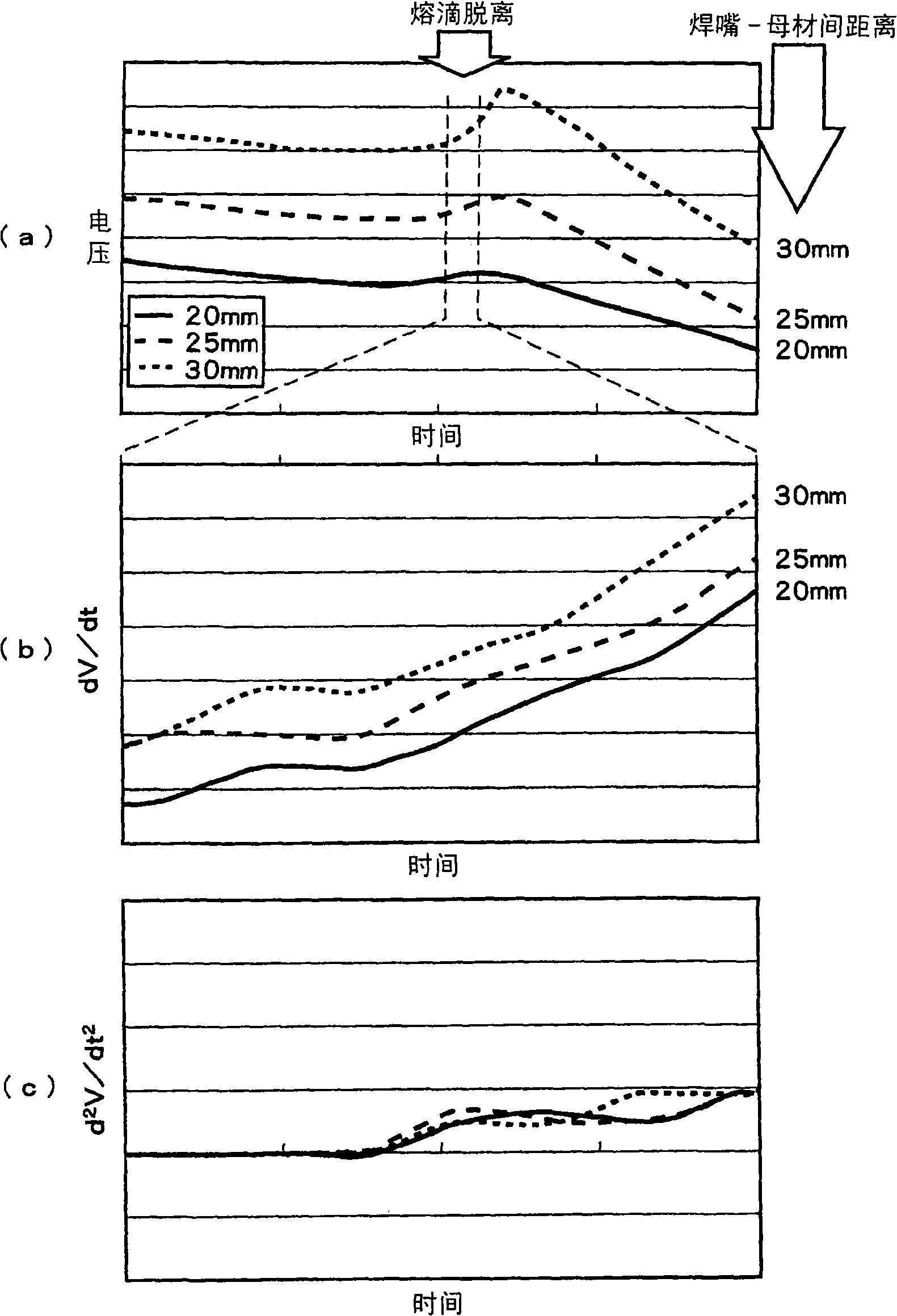
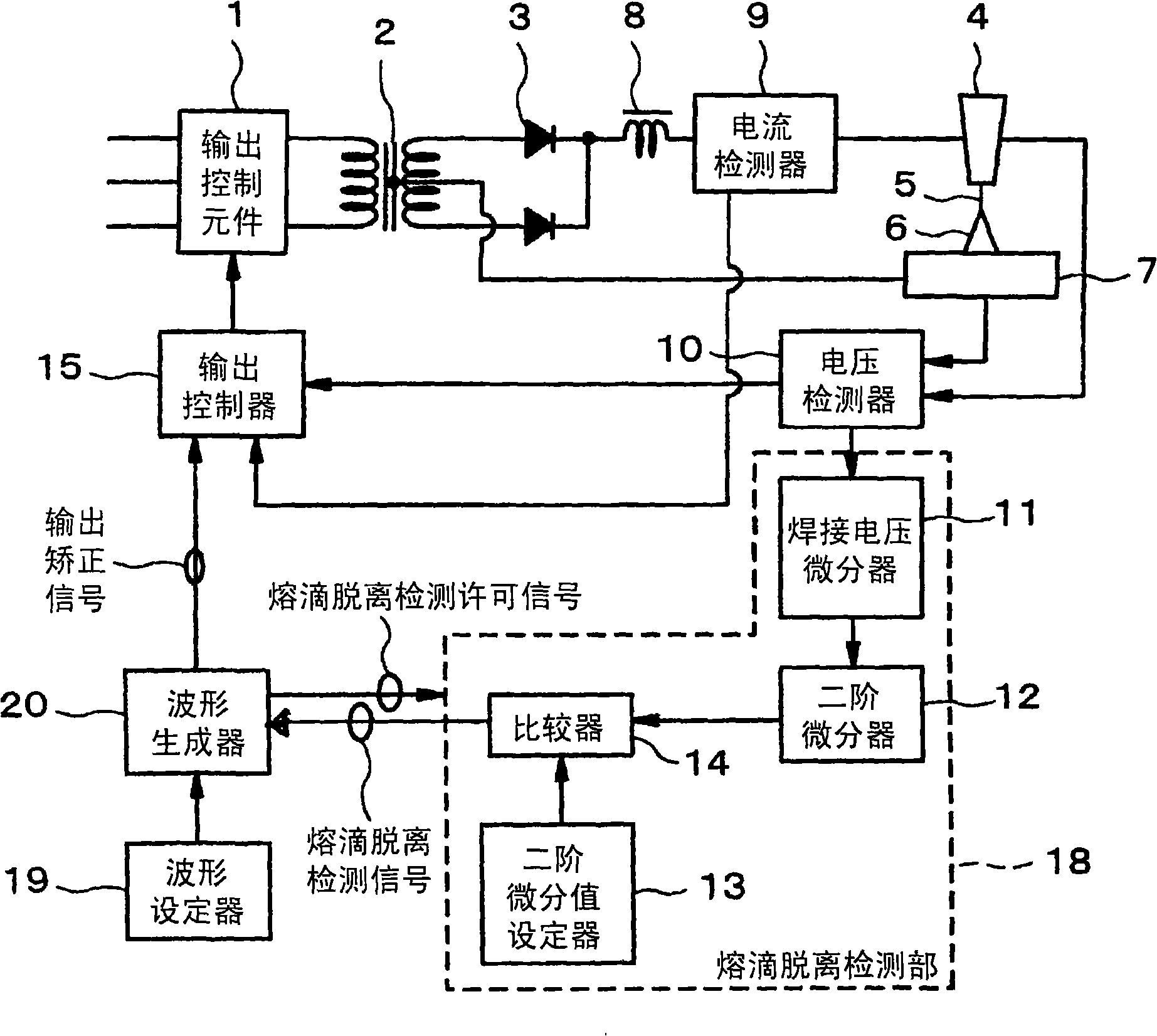
[0036] use figure 2 and image 3 The welding control devices of the first and second embodiments shown use a solid wire with a wire diameter of 1.2 mm as the consumable electrode wire, and use MAG (80% Ar+20% CO2) as the shielding gas. 2 ) gas for gas shielded arc welding. At this time, the welding current and voltage waveform and the time second order differential value of welding voltage d 2 V / dt 2 , The time second order differential value d of arc resistance 2 R / dt 2 , the detachment detection signal waveform is displayed on the Figure 4 (a), (b). Welding conditions were an average current of 240 A, an average voltage of 30 to 32 V, a welding speed of 30 cm / min, and a welding wire protrusion length of 25 mm.

[0037] exist Figure 4 Shown in (a), capture d 2 V / dt 2 or d 2 R / dt 2 The change of the welding current is switched to 120A immediately after the separation detection signal is output, and it returns to the original current (240A) state after 2.0ms. in...

Embodiment 2

[0039] Using the welding control devices of the first and second embodiments, a solid wire with a wire diameter of 1.2 mm is used as the consumable electrode wire, and CO is used as the shielding gas. 2 , for pulse arc welding. Welding current and voltage waveform in this welding, time second order differential value d of welding voltage 2 V / dt 2 , the detachment detection signal waveform is displayed on the Figure 5 (a), (b). in addition, figure 2 Indicates the pulse waveform. as it should Figure 6 As shown, the pulse peak current Ip1, Ip2 and pulse width Tp1, Tp2 are two different pulse waveforms, which will be output alternately. Figure 5 The first pulse (Ip1, Tp1) in makes the droplet detach, Figure 5 The second pulse ( Ip2 , Tp2 ) in , enables droplet formation, whereby one droplet transfer can be achieved per cycle. During the peak period or the falling slope period of the first pulse, the droplet detachment permission signal is output, and immediately after...

Embodiment 3

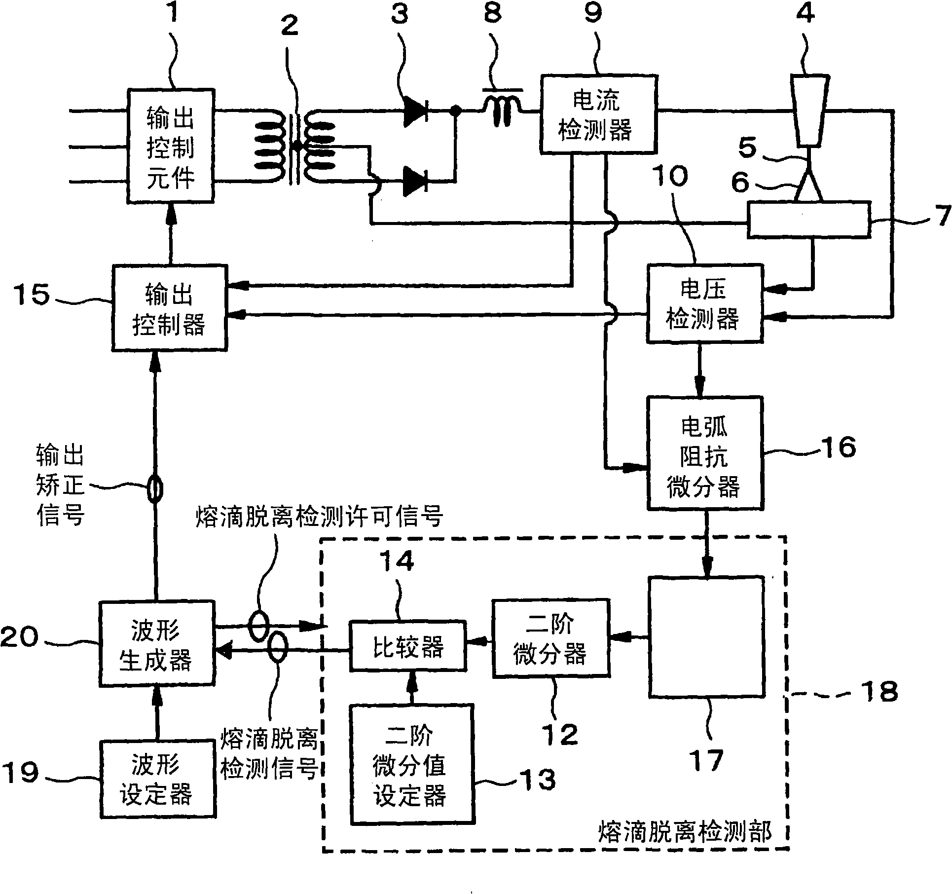
[0041] use figure 2 and image 3 The welding control device shown uses a solid wire with a wire diameter of 1.2 mm as the consumable electrode wire, and uses MAG (80% Ar+20% CO2) as the shielding gas. 2 ) gas shielding gas arc welding, and the use of 100% CO 2 Gas pulse arc welding. In downward surfacing welding, the welding is carried out under the conditions of swing width 6.0mm and swing frequency 2Hz. During welding, the protruding length of the welding wire changes at all times, compared with the existing technology (detected by the time differential value dV / dt of the voltage) ) and the present invention (time second order differential value d of the same voltage 2 V / dt 2 Detection) droplet detachment detection success rate. The average current was 300A, the voltage was set to an appropriate voltage according to each shielding gas, and the welding speed and wire protrusion length were the same as those in Example 1 and Example 2. Using a high-speed camera image, c...


PUM


Abstract

In consumable electrode type gas shielded arc welding, a time second order differential value of a welding voltage or an arc resistance is calculated. Based on the second order differential value, a detachment of a droplet or a timing just before the detachment is detected. After the droplet detachment or the timing just before the detachment is detected, a welding current value is immediately switched to a predetermined current value lower than that at the time of the detection. According to the control, even if welding conditions are changed or wire extension lengths are changed in the welding, the droplet detachment can be correctly detected.

Description

technical field [0001] The invention relates to a consumable electrode type gas shielded arc welding control device and a welding control method for arc welding using a consumable electrode in a protective gas atmosphere. Background technique [0002] In consumable electrode gas shielded arc welding, with the consumption of the electrode wire, a droplet is formed at the front end of the welding wire, and the droplet grows while being subjected to various forces such as gravity, arc reaction force, electromagnetic contraction force, and surface tension, and then detaches. , into the molten pool. However, its growth process is extremely unstable. When the molten droplet is excessively lifted and deformed, it will be affected by the arc reaction force and detached, so that it cannot transition to the molten pool in the direction of wire extension, but is scattered as large-grained spatter. Therefore, the droplet transfer period becomes irregular, which makes the behavior of th...

Claims


Application Information

Patent Timeline
Patent Type & Authority Applications(China)
IPC IPC(8): B23K9/09B23K9/173
CPCB23K9/092B23K9/173B23K9/095
Inventor 山崎圭佐藤英市中司升吾本间正浩铃木启一
Owner KOBE STEEL LTD
Why Eureka
Try Eureka