

Ultrasonic treatment device
A treatment device, ultrasonic technology, applied in the direction of manufacturing tools, generators/motors, tool holder accessories, etc., can solve the problems that it is difficult to achieve the miniaturization of endoscopes and the enlargement of ultrasonic vibrators
- Summary
- Abstract
- Description
- Claims
- Application Information
AI Technical Summary
Problems solved by technology
Method used
Image

Examples
no. 1 Embodiment approach
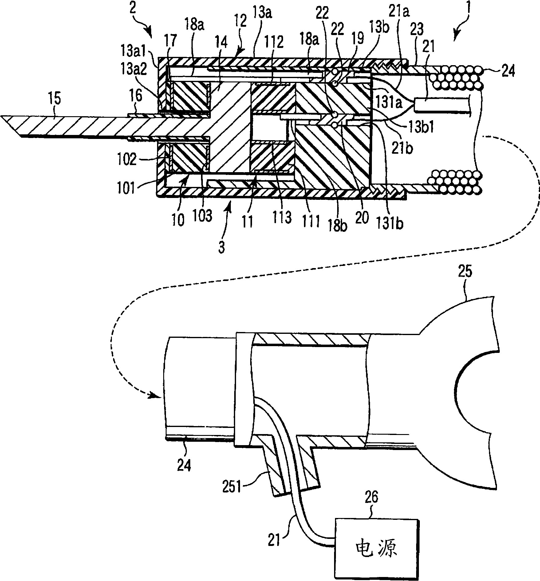
[0045] Figure 1 to Figure 6 The first embodiment of the present invention is shown. figure 1 Indicates the same as Endoscope 401 (refer to Figure 5 ) is a schematic structure of the main part of the ultrasonic therapy device 1 used together.
[0046] Figure 5 A schematic structure of the endoscope 401 is shown. The endoscope 401 has an elongated insertion portion 402 inserted into the body, and an operation portion 403 connected to the base end portion of the insertion portion 402 . The insertion part 402 has an elongated flexible tube part 404, a curved part 405 whose proximal end is connected to the front end of the flexible tube part 404, and a distal rigid part 406 whose proximal part is connected to the distal end of the curved part 405. . The bent portion 405 can be bent into a bent shape from a generally linear state extending straight. Such as Image 6 As shown, on the front end surface of the front end rigid part 406, the illumination lens of the illuminatio...
no. 2 Embodiment approach
[0098] Figure 13 And Fig. 14 shows the second embodiment of the present invention. However, in the Figure 13 In FIG. 14 , the same reference numerals are assigned to the same parts as those of the above-mentioned first embodiment, and detailed description thereof will be omitted.
[0099] Such as Figure 13 As shown, in this embodiment, the present invention is applied to the ultrasonic suction device 1A for pulverizing and emulsifying living tissue. That is, in this embodiment, the through hole 151a is provided at the axial center of the cutter 15a of the distal end treatment part 2, and the through hole 141a is also provided at the axial center of the cutter fixing member 14a as shown in FIG. 14 .
[0100] As shown in FIG. 14, the tool fixing member 14a is interposed between the said 1st and 2nd driver 10,11. The said cutter 15a protrudes from the front-end surface of this cutter fixing member 14a. A tubular hole 27 protrudes from the rear end surface of the cutter fi...
no. 3 Embodiment approach
[0110] Figure 15~ Figure 18C The third embodiment of the present invention is shown. However, in Figure 15- Figure 18C In the description, the same reference numerals are assigned to the same parts as those in the first embodiment described above, and detailed description thereof will be omitted.
[0111] As shown in FIG. 15 , this embodiment applies the present invention to an ultrasonic coagulation and incision device 1B that performs coagulation and incision processing on living tissue. That is, in the present embodiment, an openable and closable forceps piece 30 is disposed at the base end portion of the blade 15 b disposed on the distal end treatment portion 2 .
[0112] Moreover, the base end part of the cylindrical front-end|tip cover 31 is being fixed to the front-end|tip part of the outer sheath 24, such as a tight coil. As shown in FIG. 16 , the middle portion of the forceps piece 30 is rotatably supported by a front end cover 31 via a spindle pin 301 .
[0113...
PUM
 Abstract
Description
Claims
Application Information