Optically functional film, phase difference film, composition for formation of optically functional layer, and method for manufacture of optically functional film
A technology of optical functional layer and retardation film, which is applied in the direction of optics, nonlinear optics, layered products, etc., can solve the problem of white turbidity of the optical functional layer, and achieve high transparency, excellent adhesion, and excellent transparency Effect
- Summary
- Abstract
- Description
- Claims
- Application Information
AI Technical Summary
Problems solved by technology
Method used
Image
Examples
Embodiment 1
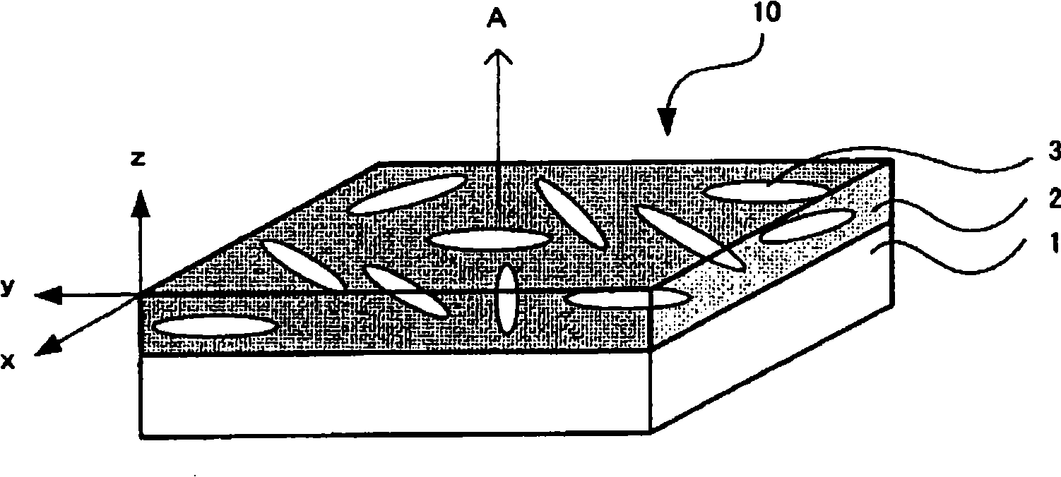
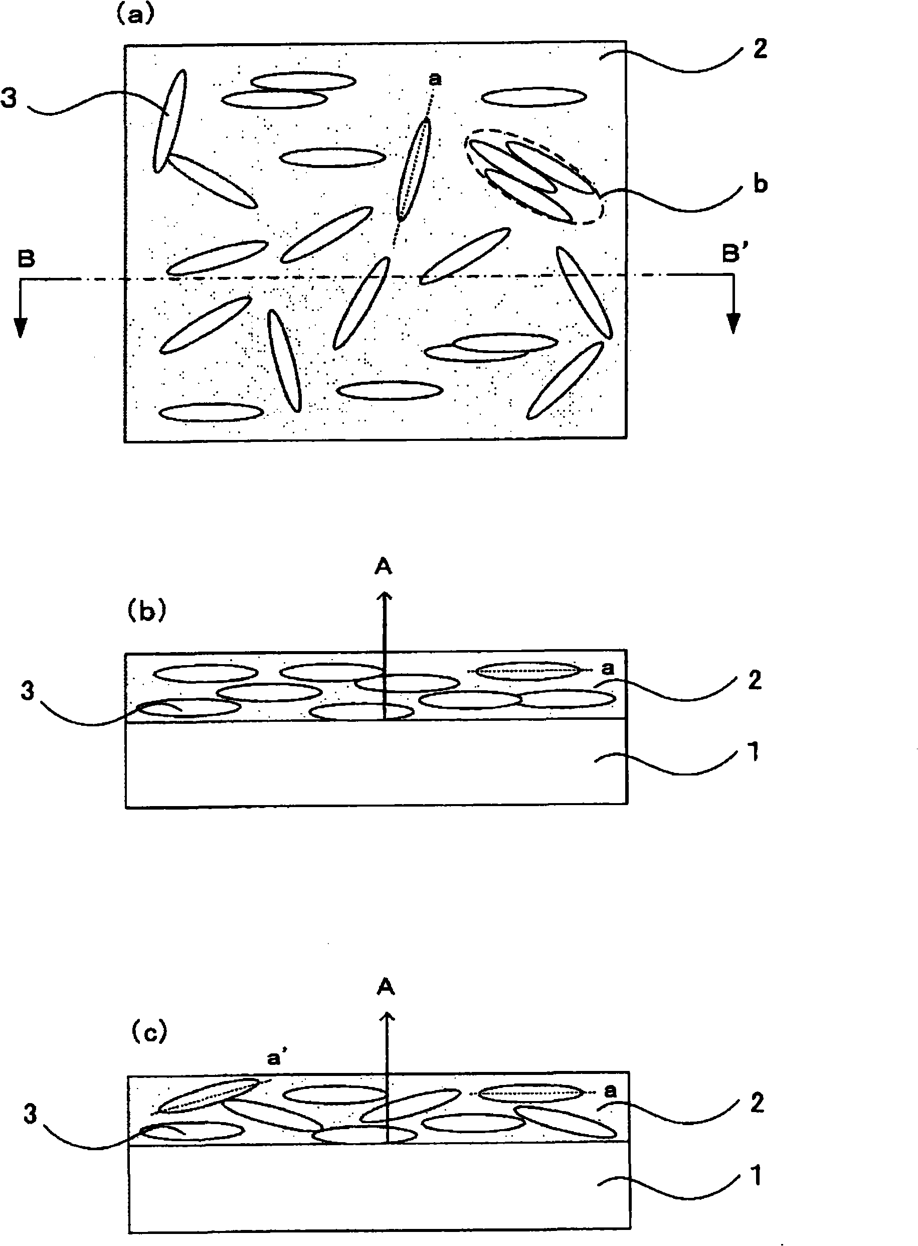
[0381] Dissolve 20% by mass of compound (I) represented by the following formula as a rod-shaped compound in cyclohexanone, and apply it on a substrate made of a TAC film (manufactured by Fujifilm Co., Ltd., trade name: TF80UL) by bar coating. It was applied so that the applied amount after drying would be 2.5 g / m2. Then, heating at 90° C. for 4 minutes, drying to remove the solvent, dipping the rod-shaped compound in the TAC film, and irradiating ultraviolet rays to the coated surface immobilized the rod-shaped compound to prepare a retardation film. The obtained retardation film was used as a sample, and the following items were evaluated.
[0382] [Chem 3]
[0383]
[0384] 1. Random uniform orientation
[0385] Rth and Re were measured for the prepared retardation film and the TD80UF by the parallel Nicol rotation method using KOBRA-WR manufactured by Oji Scientific Instruments Co., Ltd. About Rth and Re, the measured value of TD80UF was subtracted from the measured ...
Embodiment 2
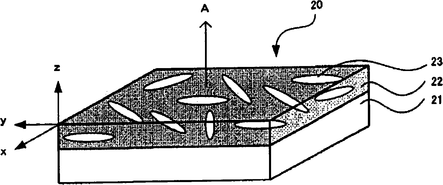
[0399] Dissolve 20% by mass of the photopolymerizable liquid crystal compound (I) represented by the above formula (I) as a rod-shaped compound in cyclohexanone, and apply it on a non-stretched COP (cycloolefin polymer) film by bar coating (manufactured by JSR Corporation, brand name: ARTON). Then, the solvent was removed by heating at 50° C. for 2 minutes. Furthermore, the above-mentioned rod-shaped compound was immobilized by irradiating ultraviolet rays to the coated surface, and then heated at 90° C. for 2 minutes to remove the residual solvent, thereby producing a retardation film. The obtained retardation film was used as a sample, and the following items were evaluated.
[0400] 1. Random uniform orientation
[0401] With respect to the retardation layer of the produced retardation film, the presence or absence of Re and the selective reflection wavelength, Rth and haze were evaluated. The measurement was performed on the entire retardation film and the above-mention...
Embodiment 3
[0414] Dissolve 20% by mass of the photopolymerizable liquid crystal compound (I) represented by the above formula (I) as a rod-shaped compound in cyclohexanone, and apply it on a uniaxially stretched COP (cycloolefin polymer) by bar coating. On a film (manufactured by JSR Corporation, trade name: ARTON). Then, the solvent was removed by heating at 50° C. for 2 minutes. Furthermore, the above-mentioned rod-shaped compound was immobilized by irradiating ultraviolet rays to the coated surface, and then heated at 90° C. for 2 minutes to remove the residual solvent, thereby producing a retardation film. The obtained retardation film was used as a sample, and the following items were evaluated.
[0415] 1. Random uniform orientation
[0416] With respect to the retardation layer of the produced retardation film, the presence or absence of selective reflection wavelength, Rth, and haze were evaluated. The measurement was performed on the entire retardation film and the above-ment...
PUM
 Abstract
Description
Claims
Application Information
 - R&D
- Intellectual Property
- Life Sciences
- Materials
- Tech Scout
- Unparalleled Data Quality
- Higher Quality Content
- 60% Fewer Hallucinations
Browse by: Latest US Patents, China's latest patents, Technical Efficacy Thesaurus, Application Domain, Technology Topic, Popular Technical Reports.
© 2025 PatSnap. All rights reserved.Legal|Privacy policy|Modern Slavery Act Transparency Statement|Sitemap|About US| Contact US: help@patsnap.com


