Supercharging type centrifugal blower fan

A centrifugal fan and fan technology, applied in the field of air purification, can solve the problems of unfavorable environmental protection, low suction, high noise, etc.

Inactive Publication Date: 2008-10-08
林钧浩
View PDF0 Cites 4 Cited by
  • Summary
  • Abstract
  • Description
  • Claims
  • Application Information

AI Technical Summary

Problems solved by technology

[0002] The various centrifugal fans used by people now have small suction, relatively poor boosting effect, relatively low efficiency, and relatively loud noise, which can neither greatly save energy nor be conducive to environmental protection.

Method used


Image

  • Supercharging type centrifugal blower fan
  • Supercharging type centrifugal blower fan
  • Supercharging type centrifugal blower fan

Examples


Embodiment 1

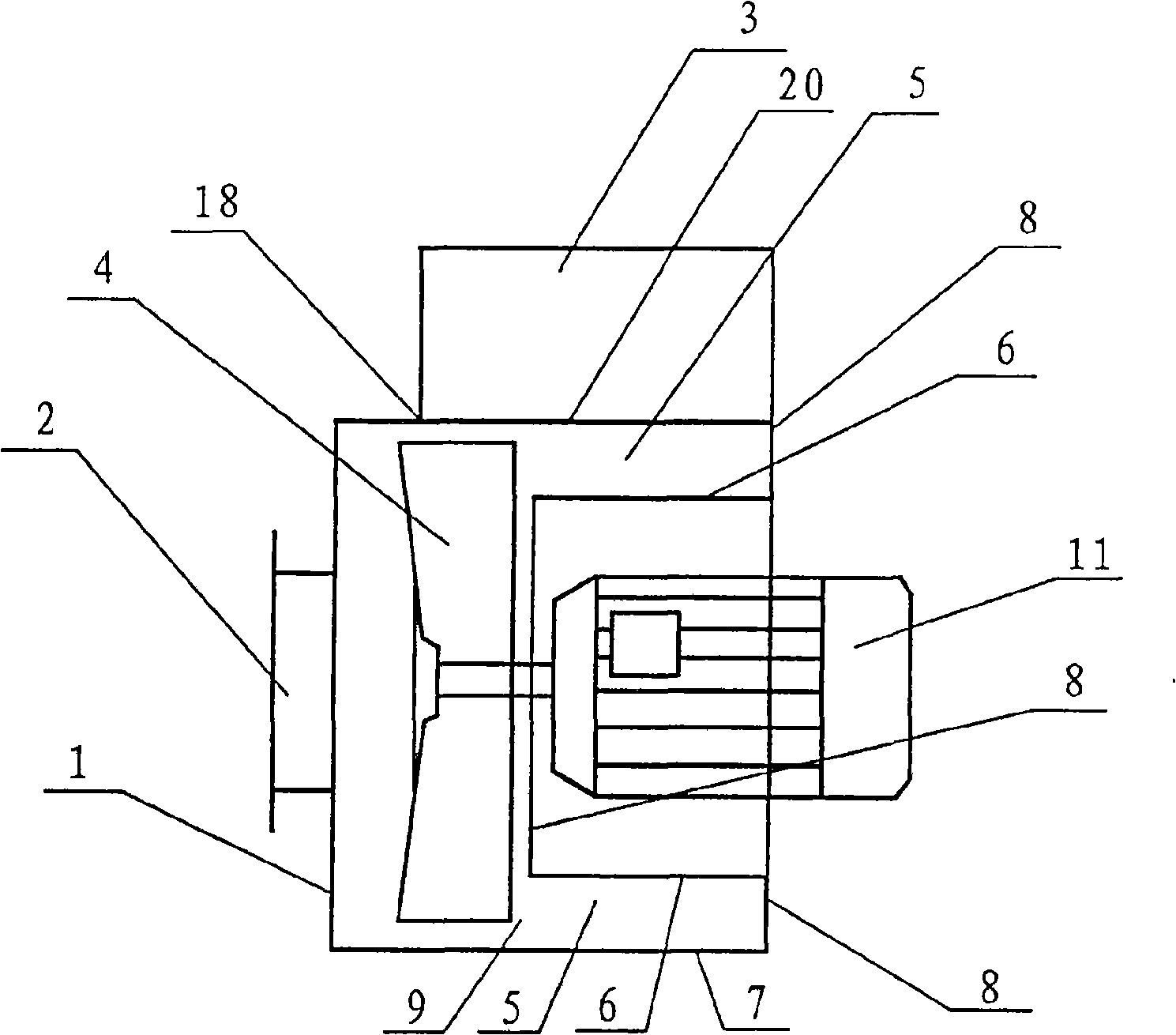
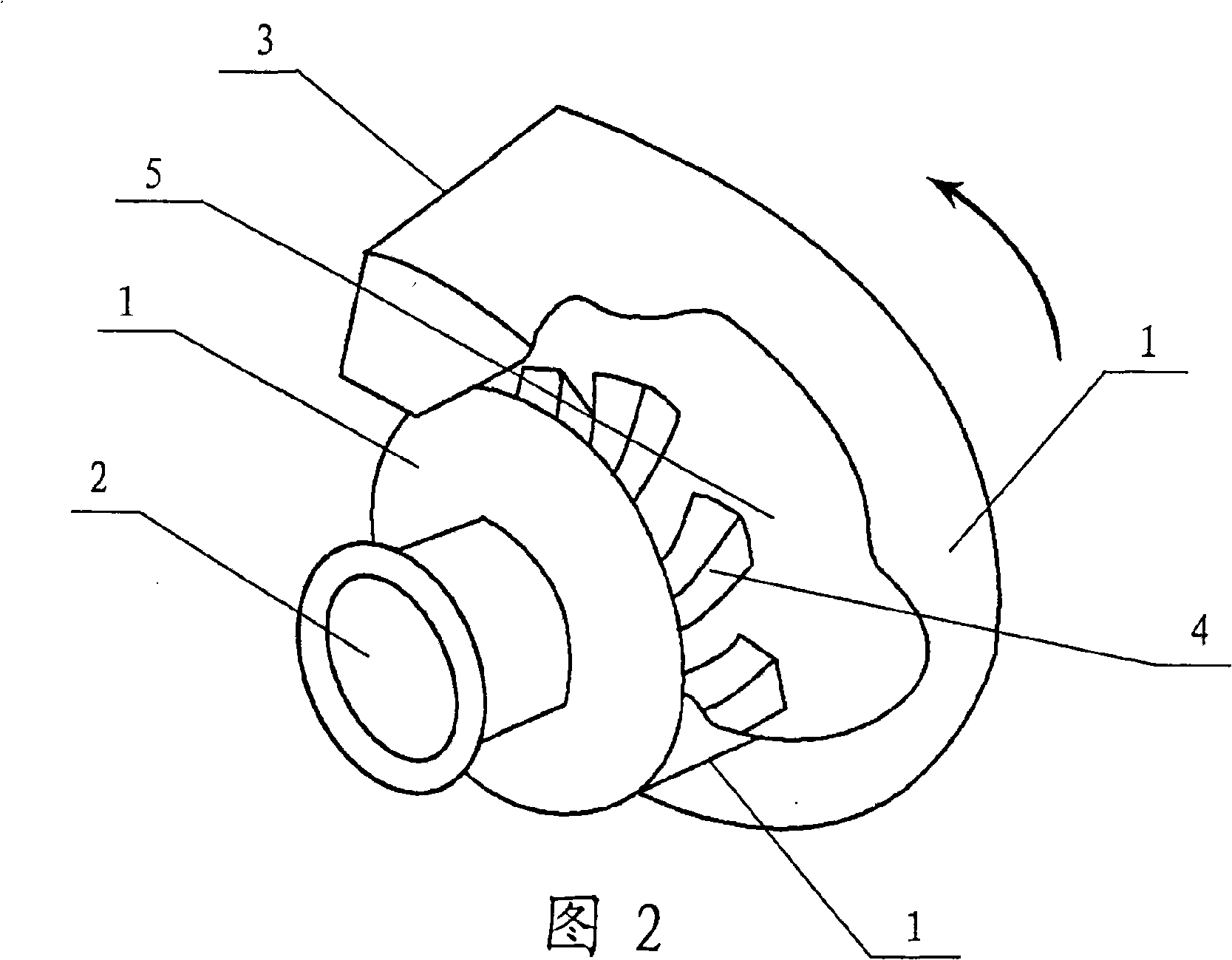
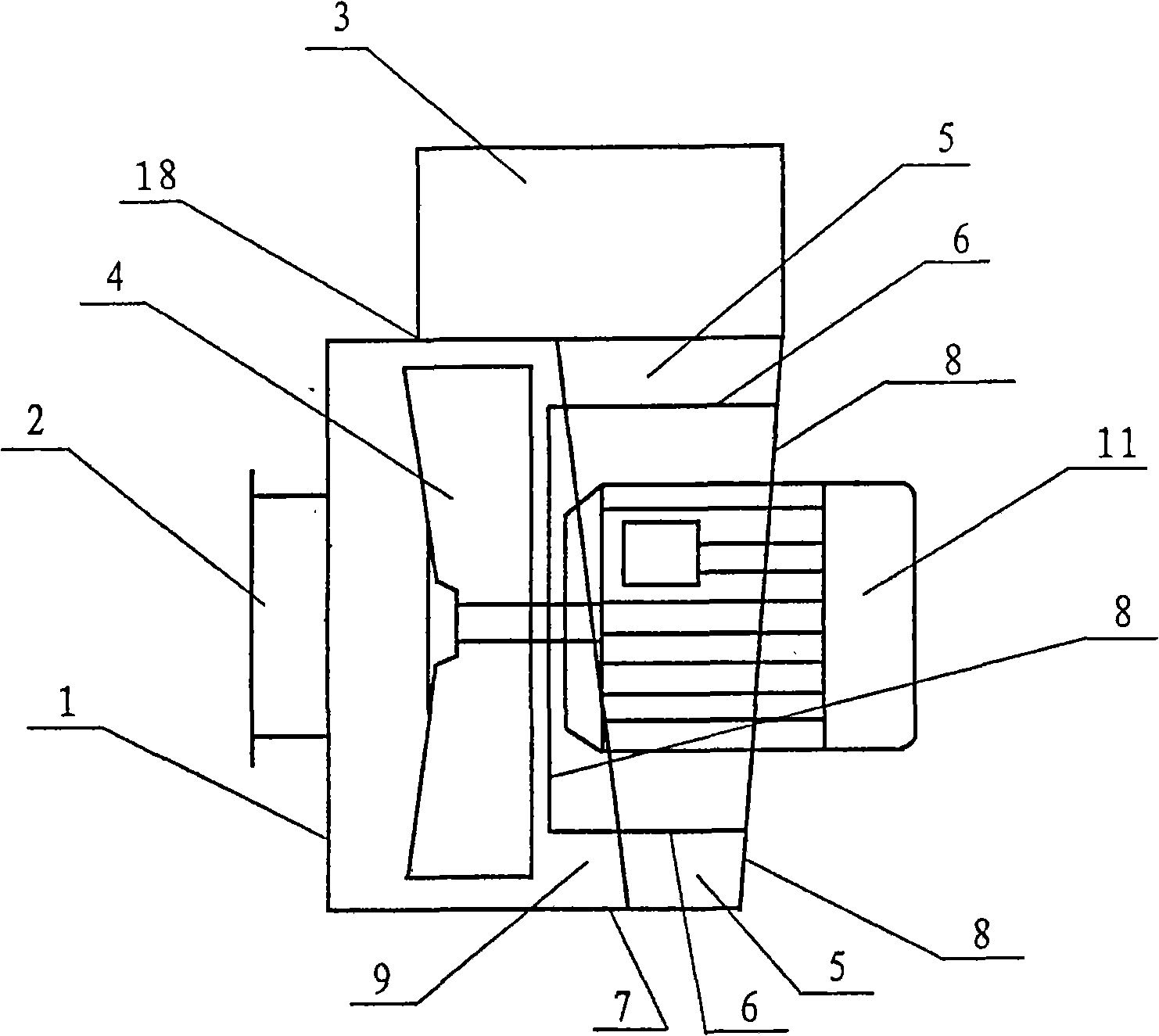
[0029] Embodiment 1, supercharged centrifugal fan (reference figure 1 ,figure 2, Figure 10 ), with a casing 1, a fan air inlet 2, a fan outlet 3, a centrifugal backflow fan impeller 4, an airflow diffusion channel 5 inside the casing, and a motor 11, and the airflow diffusion channel 5 inside the casing is located on the centrifugal backflow fan The rear shaft of the impeller at the radially rear of the impeller 4 is outside the rear shaft, and the air diffusion channel 5 inside the casing is directly connected with the fan outlet 3. The position is facing the air inlet 2 of the fan. The air flow diffuser channel 5 inside the casing is composed of three side walls, the radial inner side wall 6 of the cylindrical casing, the outer side wall 7 of the cylindrical casing, and the axial (rear) side wall 8 of the casing, forming an annular cavity structure. The front axial side of the airflow diffusion channel 5 inside the casing is provided with an inlet 9 of the airflow diffusi...

Embodiment 2

[0033] Embodiment 2, refer to image 3 , 4, 5, this example is basically the same as example 1, the difference is that the air flow diffuser channel 5 inside the casing of this example starts from the volute tongue 18 of the fan outlet 3, and gradually expands in the axial direction along the direction of the impeller, that is The axial dimension of the radial outer wall 7 of the casing is getting larger and larger.

[0034] When working, because the airflow discharged from the impeller collides with the airflow in the airflow diffuser channel inside the casing from the outer surface, the degree of disturbance is small and the eddy current is relatively weak. Therefore, it can be ensured that the airflow in the airflow diffusion channel inside the casing is decelerated and diffused steadily and fully in the airway gradually expanding in the axial direction, and finally reaches the required wind pressure. In this example, since the frictional loss and eddy current loss of the...

Embodiment 3

[0036] Embodiment 3, refer to Figure 6 , 7 , this example is basically the same as Example 1, the difference is that the air flow diffuser channel 5 inside the casing of this example starts from the volute tongue 18 of the fan outlet 3, and gradually expands radially along the impeller direction, that is, the casing axis The radial size of the (rear) sidewall 8 is getting bigger and bigger, and the radial size of the airflow diffusion channel 5 inside the casing is getting bigger and bigger. This structural formula is suitable for making the airflow diffusion channel inside the large-capacity casing.

[0037] When this example works, the high-speed airflow discharged from the impeller contacts and collides with an outer surface of the airflow in the airflow diffuser channel inside the casing, the degree of disturbance is small, and the eddy current is weak, so its friction loss and eddy current loss are relatively small. The biggest feature of the fan is that it can ensure t...


PUM


Abstract

The invention discloses a pressurized centrifugal fan which comprises a fan casing, a fan air inlet, a fan air outlet, an impeller and an airflow diffusion channel arranged inside the casing. The pressurized centrifugal fan is characterized in that: the airflow diffusion channel inside the casing is arranged at the axial lateral of the impeller at the radial rear part of the impeller and directly communicated with the air outlet of the fan; the airflow diffusion channel and the air inlet of the fan are respectively arranged at the two axial sides of the impeller; the airflow diffusion channel inside the casing is an annular channel structure shape consisting of three side walls of a radial internal side wall of the casing, a radial external side wall of the casing and an axial side wall of the casing; one axial side wall of the airflow diffusion channel inside the casing, which is faced with the impeller, is provided with an inlet of the airflow diffusion channel inside the casing; the inlet of the airflow diffusion channel inside the casing is an axial type and the outlet of the airflow diffusion channel inside the casing is a radial type; and the air outlet of the fan is a radial type. The pressurized centrifugal fan of the invention has the advantages of great suction, good pressurized effect, high mechanical efficiency, energy saving, being quiet, etc.

Description

technical field [0001] The invention relates to a pressurized centrifugal fan, which belongs to the technical field of air purification. Background technique [0002] The various centrifugal fans used by people now have small suction, relatively poor boosting effect, relatively low efficiency, and relatively loud noise, which can neither greatly save energy nor be conducive to environmental protection. Contents of the invention [0003] The purpose of the present invention is to overcome the above-mentioned shortcoming of prior art, and propose a kind of supercharging type centrifugal fan that can make the suction of centrifugal fan bigger, the supercharging effect is better, consumes less energy, efficiency is higher, and noise is lower. [0004] The purpose of the present invention can be achieved through the following measures: a pressurized centrifugal fan, including a fan casing, a fan air inlet, a fan outlet, an impeller, and an airflow diffusion channel inside the c...

Claims


Application Information

Patent Timeline
Patent Type & Authority Applications(China)
IPC IPC(8): F04D29/44F04D29/42F04D29/30
Inventor 林钧浩
Owner 林钧浩
Why Eureka
Try Eureka