Induction heating method and apparatus for axis-shaped component with raised line

A technology of induction heating and components, applied in induction heating, coil devices, etc., can solve the problems of rising time cost, difficult installation and operation, rising construction cost, etc., and achieve the effect of suppressing cost rise.

Inactive Publication Date: 2008-10-08
DAI ICHI HIGH FREQUENCY
View PDF2 Cites 0 Cited by
  • Summary
  • Abstract
  • Description
  • Claims
  • Application Information

AI Technical Summary

Problems solved by technology

In particular, such a detour type sensor has a special shape, so to use this sensor, not only it takes time to manufacture the sensor and increases the cost, but also the installation operation is not easy, and in the subsequent adjustment operation, sometimes the Man-hours such as remodeling of the trial-and-error sensor are required, which greatly increases the construction cost
[0017] In addition, in these conventional induction heating technologies, regardless of whether it is the type of feeding in the circumferential direction, the type of feeding in the axial direction, or the type in which the feeding direction is detoured from the axial direction to the When the shaft-shaped member 10 of the bar is used, there will be a problem of difficult adjustment

Method used


Image

  • Induction heating method and apparatus for axis-shaped component with raised line
  • Induction heating method and apparatus for axis-shaped component with raised line
  • Induction heating method and apparatus for axis-shaped component with raised line

Examples


Embodiment 1

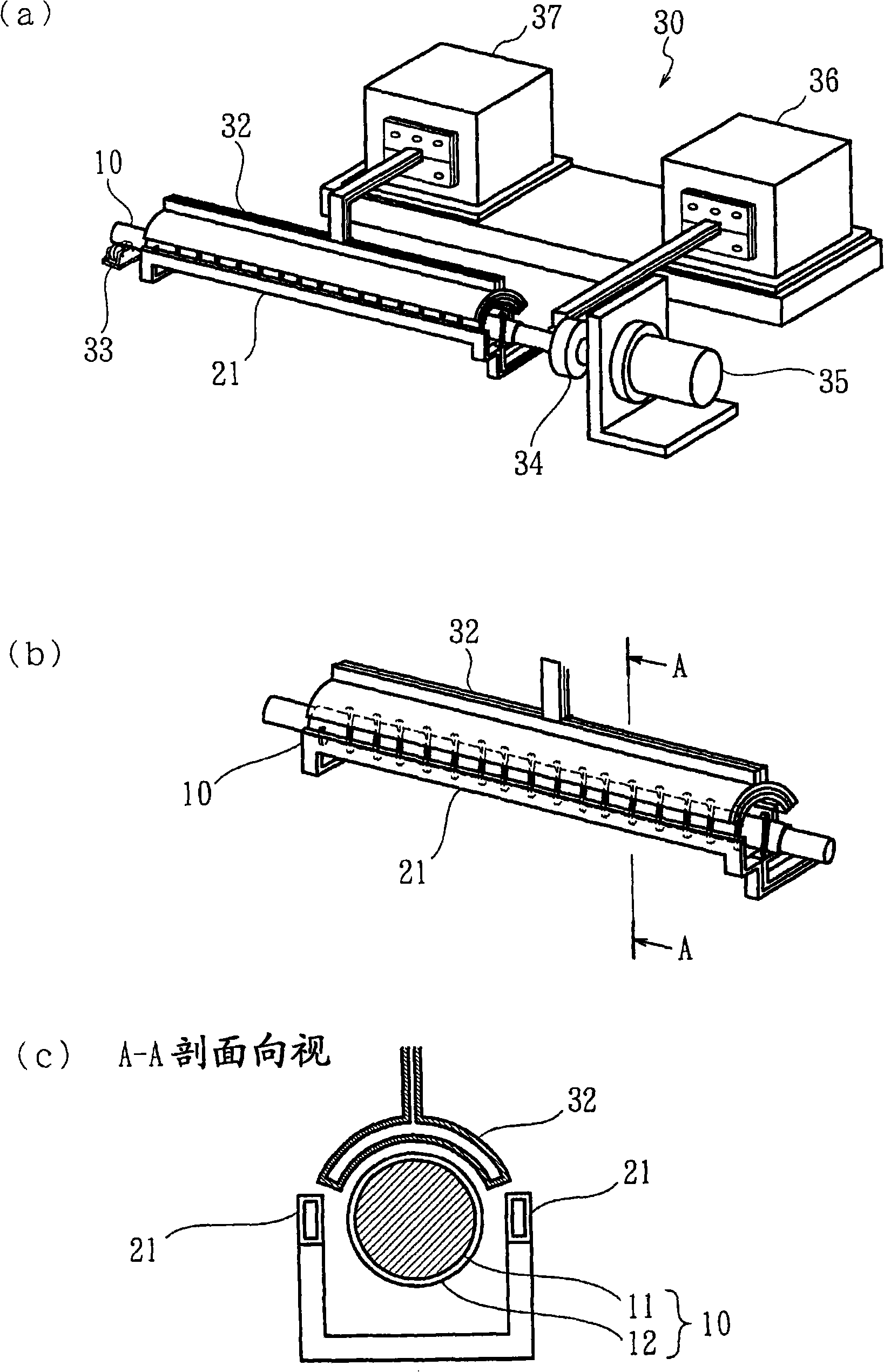
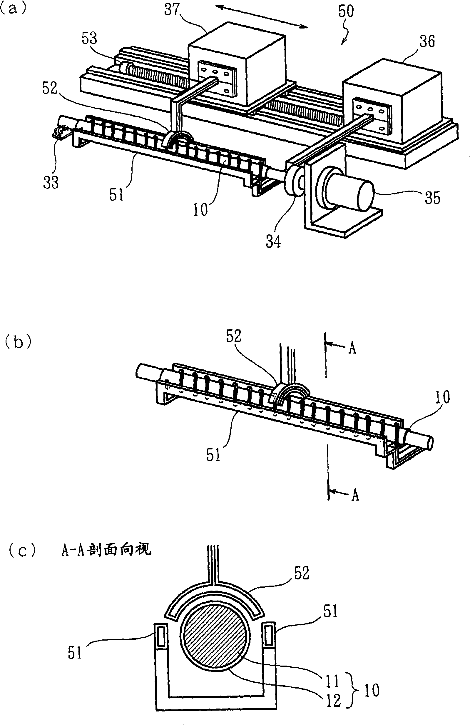
[0148] The specific structure of Embodiment 1 of the induction heating method and apparatus for a shaft-shaped member with protrusions of the present invention will be described with reference to the drawings. Figure 7 It is a plan view of the convex shaft-shaped member 10 whose shaft diameter changes. use image 3 The induction heating device 50 feeds the saddle-shaped axial direction to the induction part of the inductor 51 such as Figure 4 (b) It is formed in a zigzag shape, and the relative intervals g2, g3, and g4 are adjusted.

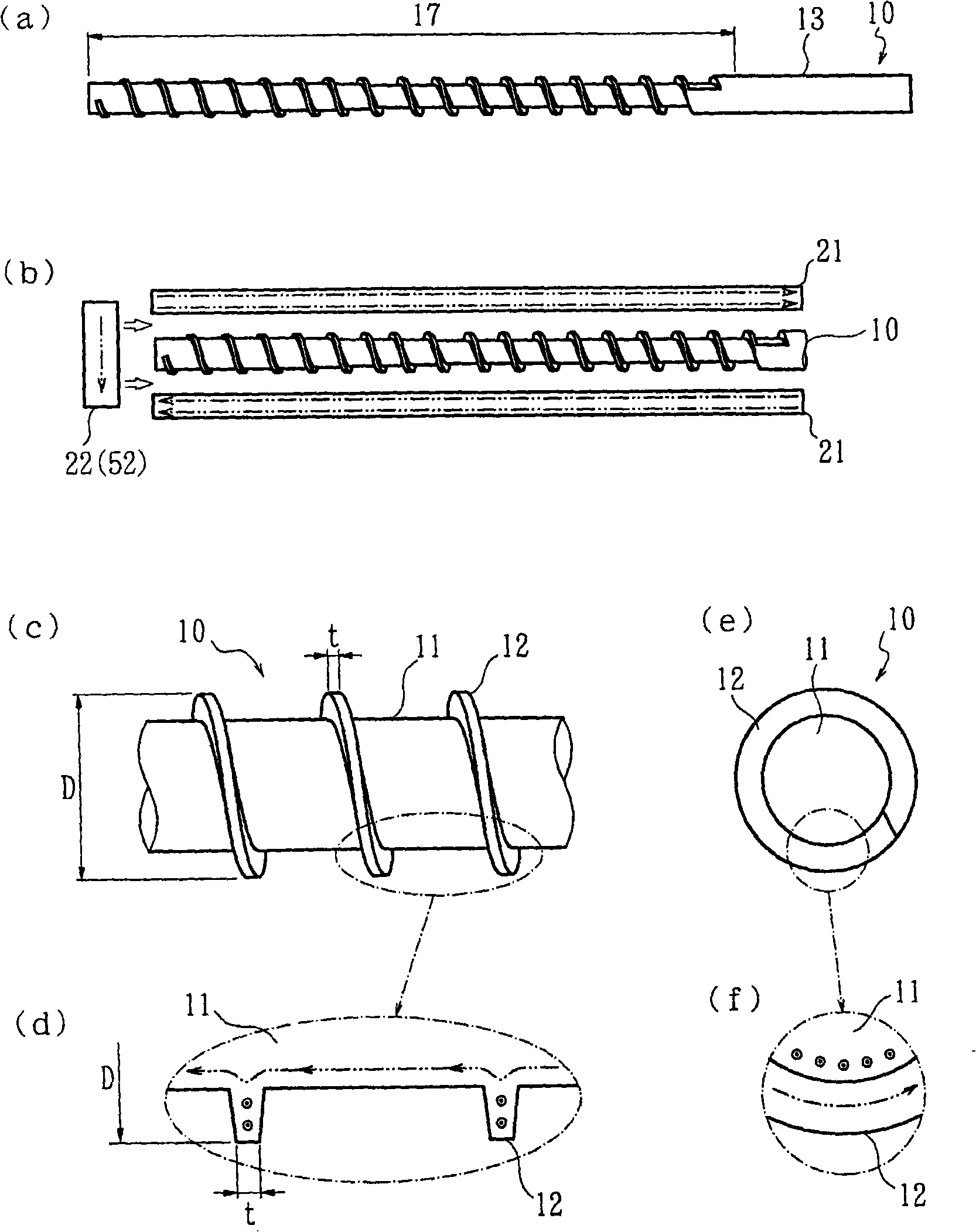
[0149] The configuration and physical properties of the ribbed shaft member 10 are as follows (refer to Figure 5 ).

[0150] Material: SCM410

[0151] Volume resistivity ρ=80(μΩ-cm)

[0152] Specific permeability μ=1 (ρ, μ are in the temperature region exceeding the magnetic transition point)

[0153] Material of the film layer coated in the previous process: Ni self-fluxing alloy (JIS SNFi2)

[0154] Film thickness covered ...

Embodiment 2

[0184] The specific structure of Embodiment 2 of the induction heating method and apparatus for a shaft-shaped member with protrusions of the present invention will be described with reference to the drawings. Figure 6 It is a plan view of the convex shaft-shaped member 10 whose shaft diameter changes. Also use here image 3 The induction heating device 50 feeds the saddle-shaped axial direction to the induction part of the inductor 51 such as Figure 4 (b) It is formed in a zigzag shape, and the relative intervals g2, g3, and g4 are adjusted.

[0185] The physical properties of the bar-shaped shaft member 10 are as follows (refer to Figure 6 ).

[0186] Material: SCM410

[0187] Volume resistivity ρ=80(μΩ-cm)

[0188] Specific permeability μ=1 (ρ, μ are in the temperature region exceeding the magnetic transition point)

[0189] Material of the film layer coated in the previous process: Ni self-fluxing alloy (JIS SNFi2)

[0190] Film thickness covered in t...


PUM


Abstract

The purpose of the invention is to: follow single heat mode with excellent production efficiency, and avoid the cost from rising to decrease the supply frequency so as to cause the axis-shaped component (10) changing along the diameter of axle to be able to easily adjust the heating homogenization. When executes induction heating to the axis-shaped component (10), the whole length of the heating area (17) is configured with axial direction feed inductor (21) and peripheral direction feed inductor (22) in moving heating mode; on one hand, the axis-shaped component (10) rotates around the axes, and on the other hand, the high frequency current is fed to the inductor (21), (22). Through the two systematizations of such heating device, the invention is able to execute the adjust of the axial direction feed inductor (21) with respect to the base circumferential face (11) and the adjust of the peripheral direction feed inductor (22) with respect to the raised line (12), so the excellent products are effectively produced with low cost.

Description

technical field [0001] The present invention relates to a method and an apparatus for inductively heating the surface layer portion of a shaft-shaped member having ridges on its outer peripheral surface. The shaft-shaped member of the convex line is the object of induction heating, and the inductor is placed close to the shaft-shaped member, and a high-frequency current is fed to the inductor (high-frequency energization), thereby generating an induced current in the surface layer of the shaft-shaped member , an induction heating method for a shaft-shaped member with convex strips for inductively heating the convex strips of the shaft-shaped member and the peripheral surface of the base, and an induction heating device suitable for implementing the method. Background technique [0002] Conventionally, as a technique for inductively heating the surface layer of a shaft-shaped member with protrusions, there are known a technique of feeding (energizing) in the circumferential d...

Claims


Application Information

Patent Timeline
Patent Type & Authority Applications(China)
IPC IPC(8): H05B6/40H05B6/02
Inventor 渡边康男多田文明
Owner DAI ICHI HIGH FREQUENCY
Why Eureka
Try Eureka