
Micro bubble machine

A bubble generating device, tiny technology, applied in indoor sanitary plumbing devices, water supply devices, sanitary equipment, etc., can solve the problems of large internal space, water bucket 126 damage, pressure increase, etc., and achieve the effect of preventing damage and being convenient to use

Active Publication Date: 2008-10-15
ダウィインダストリアルプレシジョンカンパニーリミテッド
View PDF0 Cites 0 Cited by
  • Summary
  • Abstract
  • Description
  • Claims
  • Application Information

AI Technical Summary

Problems solved by technology

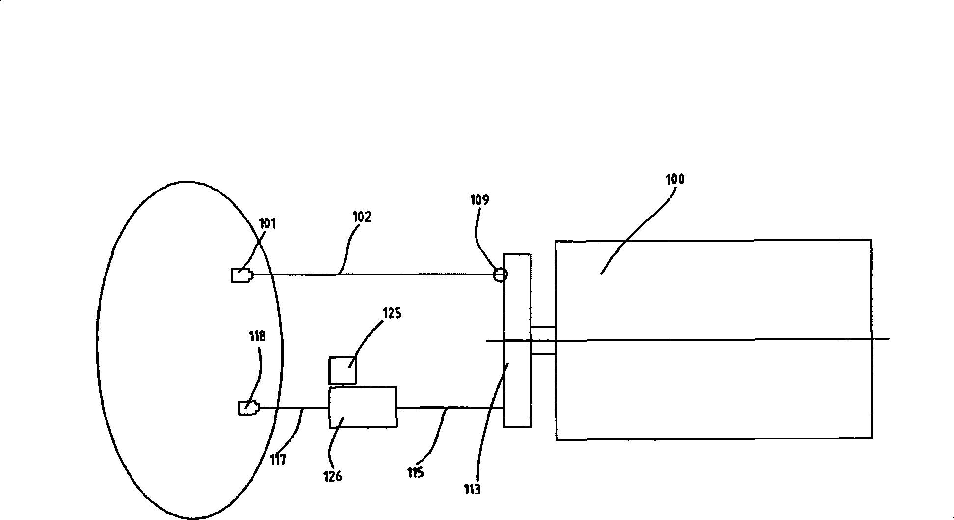
[0009] Therefore, it occupies a large internal space of the micro-bubble generating device, so that the space utilization is greatly limited
[0010] Moreover, when the micro-bubble generating device is used, foreign matter, dirt, skin cutin, etc. inside the bathtub will block the grid assembly arranged on the water outlet nozzle 118, so that the motor pump 100 will be overloaded, and the pressure of the water outlet pipeline 115 will increase. As a result, the bucket 126 is damaged, or the outlet hose 117 bursts and the washing water leaks into the micro-bubble generating device, which may even lead to dangers such as short circuits.
[0011] Moreover, in the process of using the micro-bubble generating device, when the grid assembly is blocked and needs to be replaced, because the nozzle body, nozzle cover (nozzle cover), grid assembly, and pressure plate are mutually separate structures, so There are many inconveniences in replacing the grille assembly

Method used


Image

  • Micro bubble machine
  • Micro bubble machine
  • Micro bubble machine

Examples


Embodiment Construction

[0059] Hereinafter, preferred embodiments of the present invention will be described in detail with reference to the accompanying drawings.

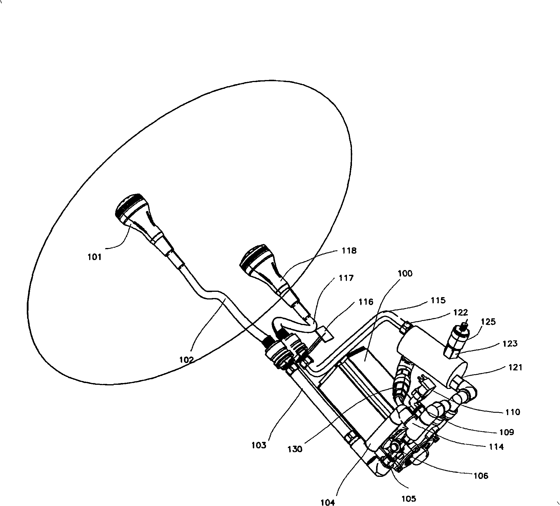
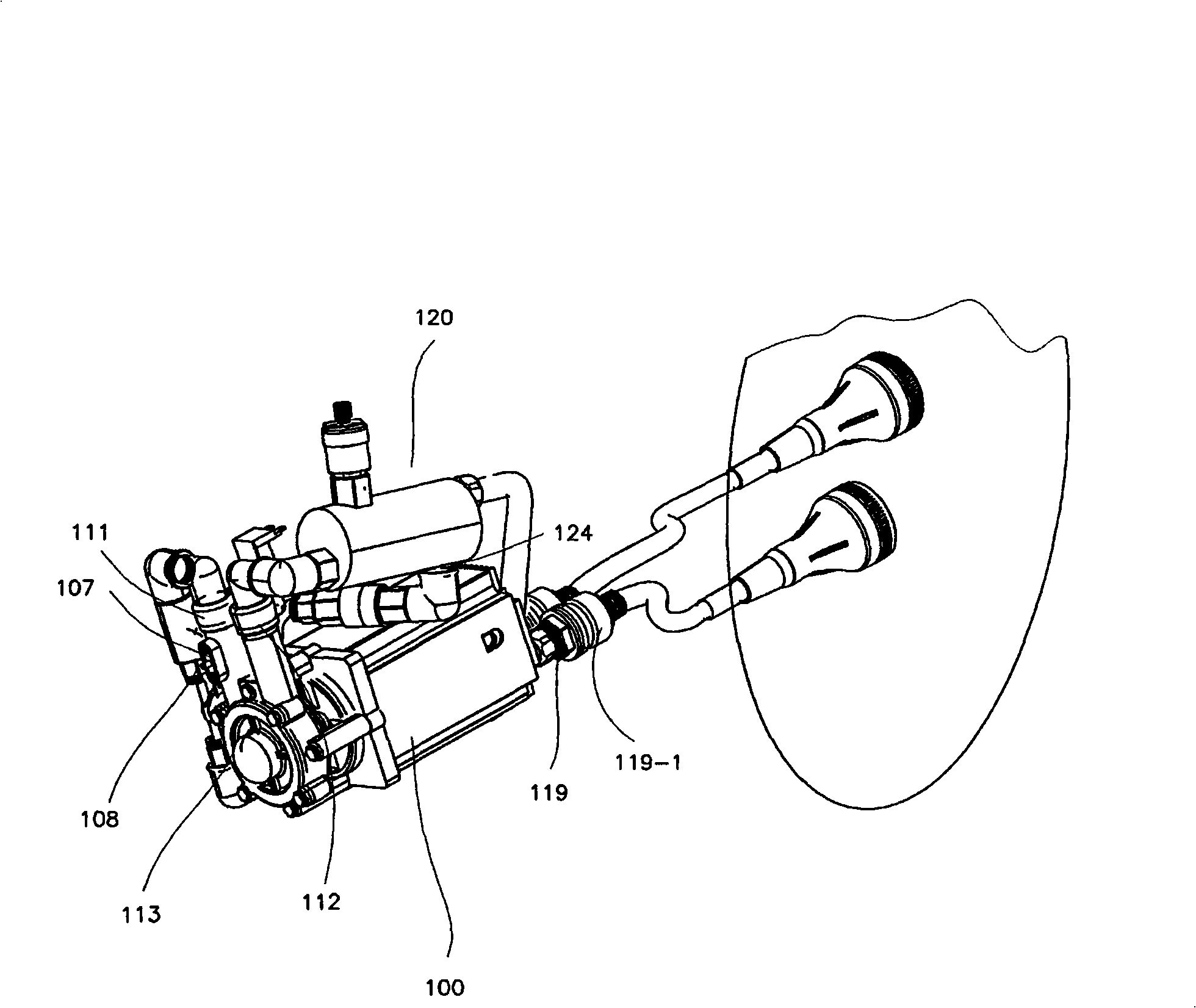
[0060] figure 2 and image 3 It is a structural diagram of the micro-bubble generating device provided by the present invention.

[0061] Such as figure 2 and image 3 As shown, the water inlet pipe 103 of the motor pump 100 of the present invention is connected to the water inlet hose 102, and the water inlet hose 102 is connected to the water inlet nozzle 101, and the inside of the water inlet nozzle 101 is provided with a filter when the washing water is sucked. Filter for foreign matter.

[0062] A check valve 119 is provided between the water inlet pipe 103 and the water inlet hose 102 of the motor pump 100 to prevent the washing water flowing into the water inlet pipe 103 , the main water inlet pipe 104 and the auxiliary water inlet pipe 105 from flowing to the outside. This is to assist the self-priming of the motor pump 10...


PUM


Abstract

The invention relates to a tiny bubble generation device, more particularly to a tiny bubble generation device using a non-self-absorbing electric engine pump. The tiny bubble generation device comprises: a multifunctional water barrel communicated with an pump outlet connected to the electric engine pump; a pressure valve communicated with a lower portion hole of the multifunctional water barrel; a startup water pipe of the electric engine pump communicated with the pressure valve; an exhaust valve communicated with an upper portion hole of the multifunctional water barrel. In accordance with the invention, if the air enters into an water inlet pipe, the electric engine pump ceases operation to avoid the idle running of the electric engine pump, and further to avoid the damage to the components of the electric engine pump, and even the non-self-absorbing electric engine pump is utilized, the self-absorption effect can be realized with the water within the multifunctional water barrel, such that the device can be used conveniently without the additional startup water.

Description

technical field [0001] The invention relates to a micro-bubble generating device, in particular to a micro-bubble generating device using a non-self-priming motor pump. Background technique [0002] A conventional microbubble generator is disclosed in Korean Patent Publication No. 2003-0010685. [0003] figure 1 This is a structural diagram of a conventional microbubble generator using a non-self-priming motor pump. [0004] The micro-bubble generating device puts the water inlet nozzle 101 and the water outlet nozzle 118 into the water in the bathtub and then starts the motor pump 100 to circulate the washing water, and forms an air suction port 109 on the pump inlet side to suck in air while sucking the washing water, The washing water and air flowing into the motor pump 100 flow through the bucket 126 provided with an air vent 125 and are pressurized by the pressure plate provided at the water outlet nozzle 118, and then forcefully hit the grid assembly to generate tiny...

Claims


Application Information

Patent Timeline
Patent Type & Authority Applications(China)
IPC IPC(8): B01F5/00B01F3/04B01F25/60
CPCA47K3/10A61H23/04E03C1/084C02F2303/26B01F23/231
Inventor 金信淑
Owner ダウィインダストリアルプレシジョンカンパニーリミテッド
Learn More