Floating guiding hydraulic cylinder

A floating guide, hydraulic cylinder technology, applied in the direction of fluid pressure actuation devices, etc., to achieve the effect of reducing machining accuracy requirements, reducing wear and improving working life

Inactive Publication Date: 2011-07-06
CONTINUOUS CASTING TECH ENG OF CHINA
View PDF0 Cites 0 Cited by
  • Summary
  • Abstract
  • Description
  • Claims
  • Application Information

AI Technical Summary

Problems solved by technology

As the working pressure of the oil cylinder increases, the tightening force of the sealing ring on the piston rod also increases. In the case of high-speed reciprocating motion, the sealing ring guide will be worn, heated, and even damaged.

Method used


Image

  • Floating guiding hydraulic cylinder
  • Floating guiding hydraulic cylinder
  • Floating guiding hydraulic cylinder

Examples


Embodiment Construction

[0015] The present invention will be described in further detail below in conjunction with the accompanying drawings and embodiments.

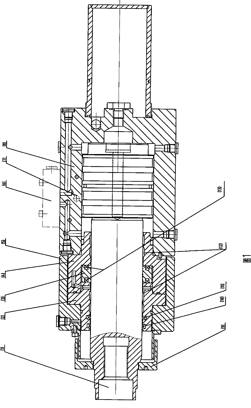
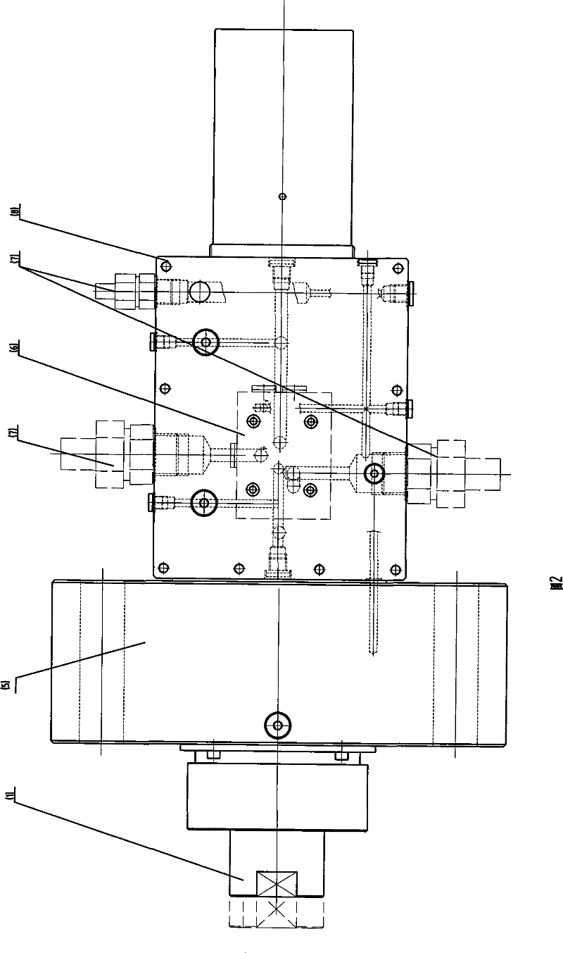
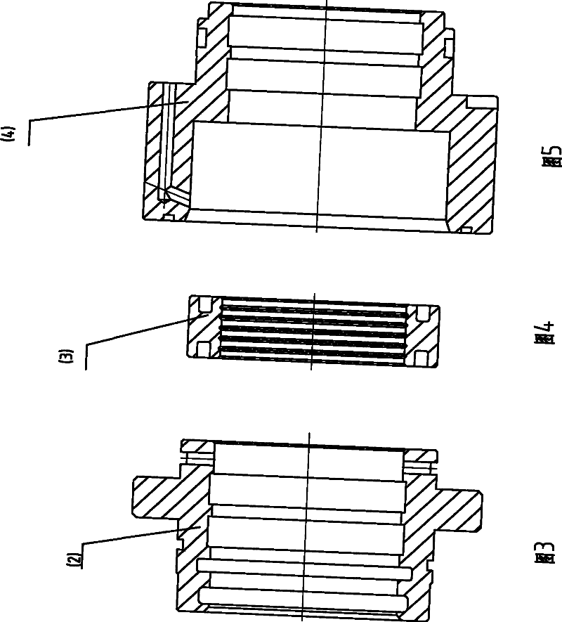
[0016] figure 1 Instructions marked in the middle: piston rod 1, left cylinder liner 2, floating sleeve 3, right cylinder liner 4, front gland 5, hydraulic control valve 6, external oil circuit 7, cylinder barrel 8, protective cover 9, dustproof ring 10 , Sealing ring 11, guide ring 12, floating sleeve sealing ring 13.

[0017] Examples of the present invention are Figure 1 to Figure 5 shown.

[0018] see figure 1 , the embodiment of the present invention floating guide hydraulic cylinder, including piston rod 1, front gland 5, hydraulic control valve 6, external oil circuit 7, cylinder 8, sealing ring 11, guide ring 12, is characterized in that: the hydraulic cylinder The cylinder liner is composed of the left cylinder liner 2, the floating liner 3 and the right liner 4 which are set on the outer surface of the piston rod 1. The floati...


PUM


Abstract

The present invention discloses a floating guide hydraulic cylinder comprising a piston rod, a front gland, a hydraulic control valve, an external oil path, a cylinder barrel, sealing rings and a guide ring, and the hydraulic cylinder is characterized in that a cylinder sleeve of the hydraulic cylinder consists of a left cylinder sleeve, a floating sleeve and a right cylinder sleeve, wherein the left cylinder sleeve is sleeved on an outer surface of a piston rod, the floating sleeve is arranged between the left cylinder sleeve and the right cylinder sleeve, the floating sleeve is connected with the left cylinder sleeve and the right cylinder sleeve by the sealing rings of the floating sleeve at two ends. The outer diameter of the floating sleeve is smaller than the inner diameter of the right cylinder sleeve corresponding to the floating sleeve. Clearance between the floating sleeve and the piston rod is sealed to form pressure fall, the sealing member between the left cylinder sleeve and the piston rod is in a low pressure state, which can realize better sealing and can work efficiently in a long time. The clearance of the floating sleeve is adjusted properly so that the pressure fall can be controlled well; because of presence of the floating sleeve, demand of processing precision of a matching member is reduced, thereby having low cost and convenient popularization.

Description

technical field [0001] This technology is widely used in places where hydraulic cylinders for hydraulic drives, servo cylinders and similar actuators are used. Due to its general processing accuracy requirements and long service life, it is especially suitable for application in the metallurgical industry where the environment is harsh and replacement is inconvenient. Background technique [0002] Most of the guides commonly used in hydraulic cylinders and servo cylinders at home and abroad are sealing rings, but the sealing materials and processing and treatment methods are continuously improved to improve the service life, which can basically meet the use requirements. As the working pressure of the oil cylinder increases, the tightening force of the sealing ring on the piston rod also increases. In the case of high-speed reciprocating motion, the sealing ring guide will be worn, heated, and even damaged. Contents of the invention [0003] The purpose of the present ...

Claims


Application Information

Patent Timeline
Patent Type & Authority Patents(China)
IPC IPC(8): F15B15/20F15B15/00
Inventor 周国强阎瑞河钟光
Owner CONTINUOUS CASTING TECH ENG OF CHINA
Why Eureka
Try Eureka