In situ nanometer stretching experiment measuring detection device

A detection device and measurement device technology, applied in the direction of the measurement device, the use of a stable tension/pressure test material strength, instruments, etc., to achieve a good effect of theoretical significance

Inactive Publication Date: 2008-10-15
HARBIN INST OF TECH
View PDF0 Cites 52 Cited by
  • Summary
  • Abstract
  • Description
  • Claims
  • Application Information

AI Technical Summary

Problems solved by technology

[0003] The purpose of the present invention is to solve the existing problem that the measurement of mechanical properties and the detection of micr

Method used


Image

  • In situ nanometer stretching experiment measuring detection device
  • In situ nanometer stretching experiment measuring detection device
  • In situ nanometer stretching experiment measuring detection device

Examples


specific Embodiment approach 1

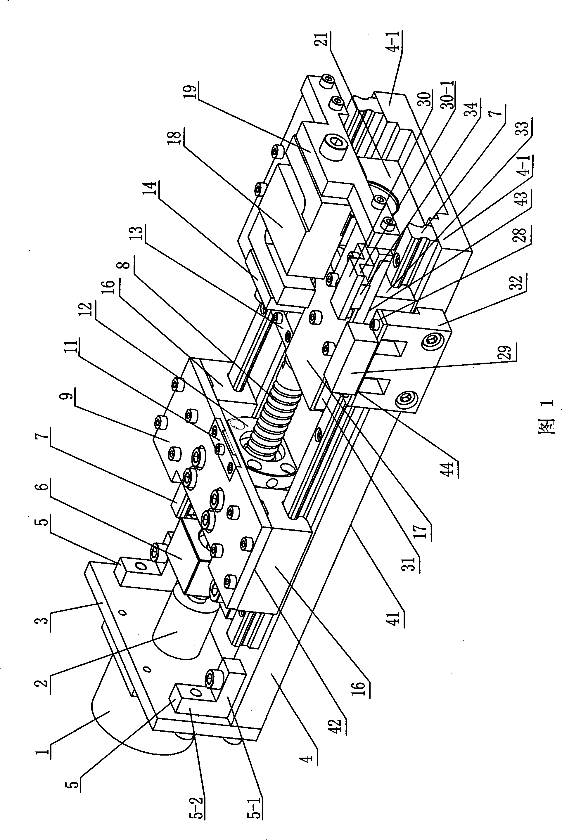
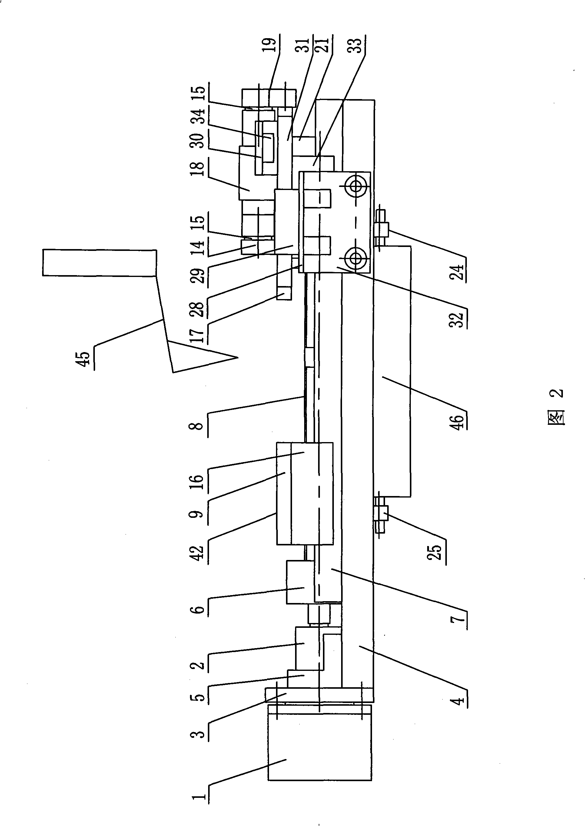
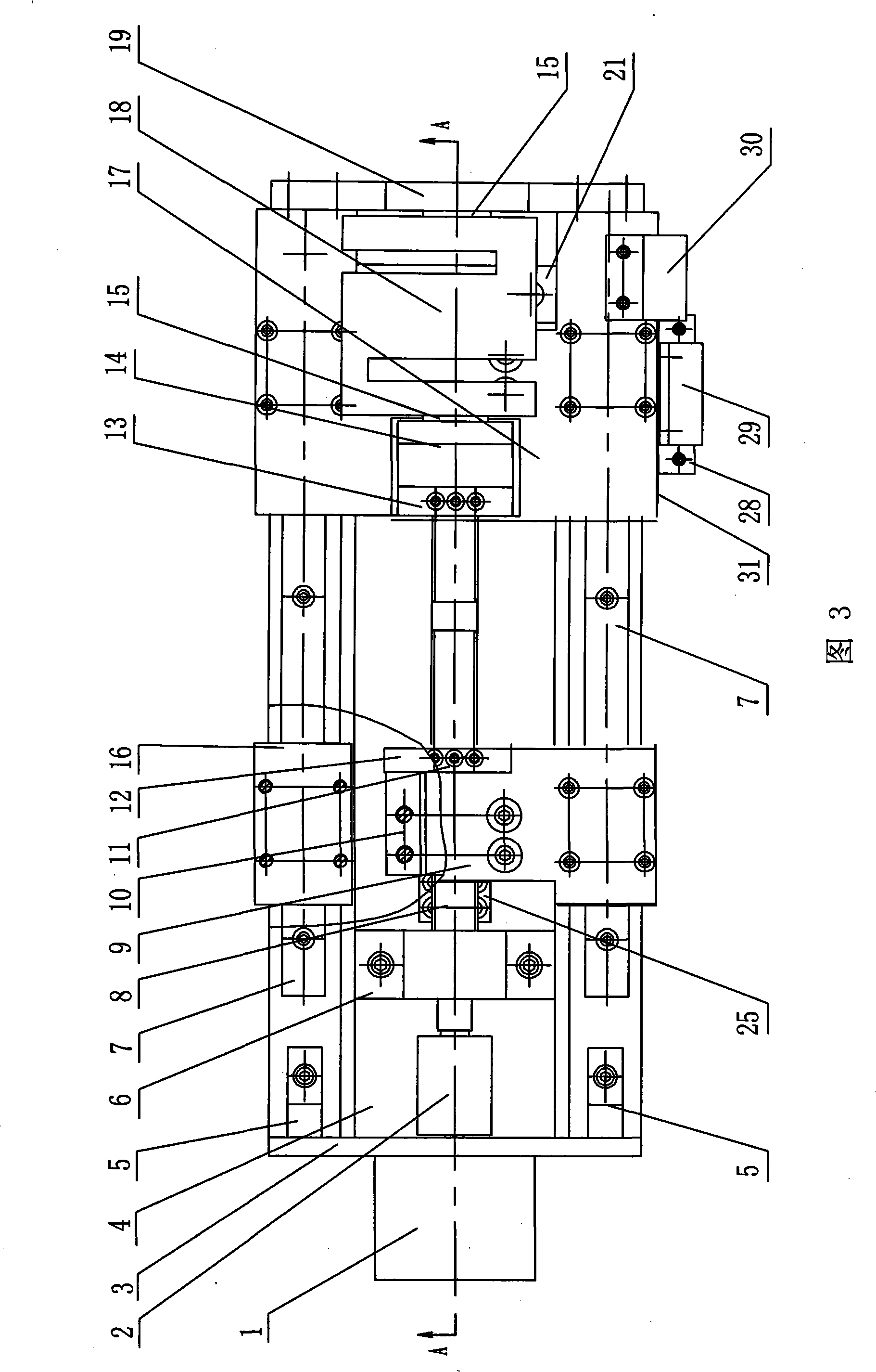
[0007] Specific implementation mode one: in conjunction with Fig. 1~ Figure 7 Describe this embodiment, this embodiment is made up of detection device and tensile measuring device 41, and described detection device is made up of detection system 45 and workbench 46, and described detection system 45 is screwed on the top of workbench 46; It is characterized in that The tensile measurement device 41 includes a stepper motor 1, a shaft coupling 2, a frame side plate 3, a frame bottom plate 4, a guide rail 7, a left and right screw screw 8, a left frame group 42, a left clamp 11, and a right clamp 13 , right fixture connection block 14, right vehicle frame group 43, force sensor 18, force sensor holder 19, bearing seat 21, reading device 44, reference device support 30, grating ruler 31 and reference device 34, described left and right screw The left side of 8 is a right-handed thread, and the right side of the left-handed screw 8 is a left-handed thread. A stepper motor 1 is f...

specific Embodiment approach 2

[0008] Specific embodiment two: in conjunction with Fig. 1~Fig. 4 and Figure 6 Describe this embodiment, the left vehicle frame group 42 of this embodiment is made up of left slider 16, left vehicle frame 9, left nut support 10 and left flange nut 12, the outer wall of described left flange nut 12 A left screw support 10 is fixedly installed on the top, and the left screw support 10 is fixed on the lower end surface of the left vehicle frame 9 , and the left vehicle frame 9 is fixed on the upper end surface of the left slide block 16 . With such arrangement, the left frame group 42 runs more smoothly. Other components and connections are the same as those in the first embodiment.

specific Embodiment approach 3

[0009] Specific implementation mode three: in combination with Fig. 1 to Fig. 4 and Figure 7 Describe this embodiment, the right vehicle frame group 43 of this embodiment is made up of right slider 33, right vehicle frame 17, right nut support 22 and right flange nut 23, the outer wall of described right flange nut 23 A right screw nut support 22 is fixedly installed on the top, and the right screw nut support 22 is fixed on the lower end surface of the right vehicle frame 17, and the right vehicle frame 17 is fixed on the upper end surface of the right slide block 33. With such arrangement, the right frame group 43 runs more smoothly. Other components and connections are the same as those in the first embodiment.


PUM


Abstract

The invention relates to a tension experiment measuring and detecting device, in particular to an in-situ nano tension experiment measuring and detecting device. The invention solves the problem in the prior art that measurement of mechanical properties and detection of micro-morphology are two independent and separate processes. An output shaft of a stepper motor (1) of the device is fixedly connected with a coupler (2); a guide rail (7) is fixed on a stander soleplate (4); a left frame set (42) and a right frame set (43) are arranged on the guide rail (7); both ends of a left and right rotary screw (8) are respectively connected with the coupler (2) and a bearing support (21); a left end face and a right end face of a force sensor (18) are respectively and fixedly connected with a right clamp connecting block (14) and a force sensor holder (19); a reading device (44) is arranged on the stander soleplate (4); and a tension measuring device (41) is fixed on a worktable (46) of the detection device. The in-situ nano tension experiment measuring and detecting device promotes further development of the research area of dynamic observation required on the micro-morphology variation of a sample under the state of stress, and has important theoretical significance and good application prospect on measurement of the mechanical properties and detection of the micro-morphology of composite functional nanophase materials.

Description

technical field [0001] The invention relates to a tensile test measuring and detecting device. Background technique [0002] Usually, the mechanical performance of nanocomposite functional materials is tested by tensile experiments, and the mechanical performance parameters such as fracture characteristics and elastic modulus of materials are analyzed by obtaining real-time stress-strain curves. The microscopic morphology of nanocomposite functional materials has a great influence on its mechanical properties. At present, scanning electron microscopy (SEM) and atomic force microscopy (AFM) are mainly used to characterize the microstructure of nanocomposite functional materials. People analyze the data obtained from the two experimental methods of tensile experiment and microstructure detection, and then optimize the production process of nano functional materials. In this process, the measurement of mechanical properties and the detection of microscopic morphology are two i...

Claims


Application Information

Patent Timeline
IPC IPC(8): G01N3/08G01N13/00
Inventor 闫永达孙涛胡振江赵学森周琴张龙江董申
Owner HARBIN INST OF TECH
Why Eureka
Try Eureka