Gas measuring method and its device

A gas measurement and gas technology, applied in the measurement of color/spectral characteristics, etc., can solve the problems of difficult installation and debugging, limited measurement accuracy, limited measurement optical path, etc., to achieve low cost, reduce optical noise, and reduce optical noise. Effect

Active Publication Date: 2008-10-15
FOCUSED PHOTONICS
View PDF0 Cites 14 Cited by
  • Summary
  • Abstract
  • Description
  • Claims
  • Application Information

AI Technical Summary

Problems solved by technology

However, the transmitting unit and receiving unit of the measuring device are located on both sides of the measured gas, which is difficult to install and debug; and it is inconvenient to maintain; the measuring optical path of the device is limited, depending on the specific on-site working conditions, which limits the measurement precision; the device is also typically bulky and inflexible

Method used


Image

  • Gas measuring method and its device
  • Gas measuring method and its device
  • Gas measuring method and its device

Examples


Embodiment 1

[0040] The following sections of this example describe a gas measurement device and method:

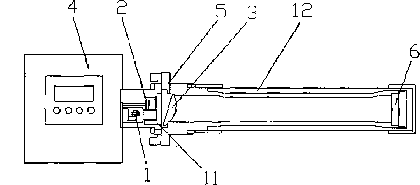
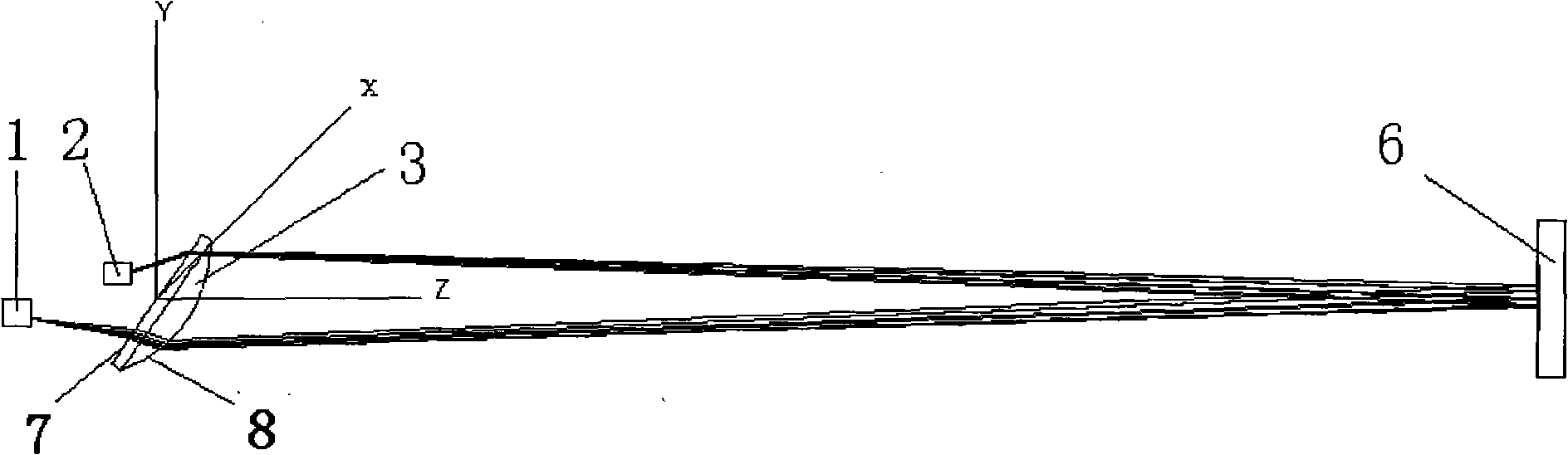
[0041] Such as figure 1 , figure 2 As shown, the gas measurement device includes a laser 1 , a sensor 2 , a plano-convex lens 3 , a concave mirror 6 , a support device 5 and an analysis unit 4 . The supporting device 5 is composed of a fixed cavity 11 and a measuring channel 12. One side of the measuring channel 12 is connected to the fixed cavity 11, and the other side is provided with a concave mirror 6. The laser 1, the plano-convex lens 3 and the sensor 2 are all installed in the fixed cavity 11. , the plano-convex lens 3 separates the laser 1, the sensor 2 from the gas in the measurement channel.

[0042] The laser 1 and the sensor 2 are arranged on the same side of the plano-convex lens 3, the plane of the plano-convex lens 3 faces the laser 1 and the sensor 2, and the position of the obliquely installed laser 1 in the Y-axis direction is lower than the sensor 2. Sensor 2 is...

Embodiment 2

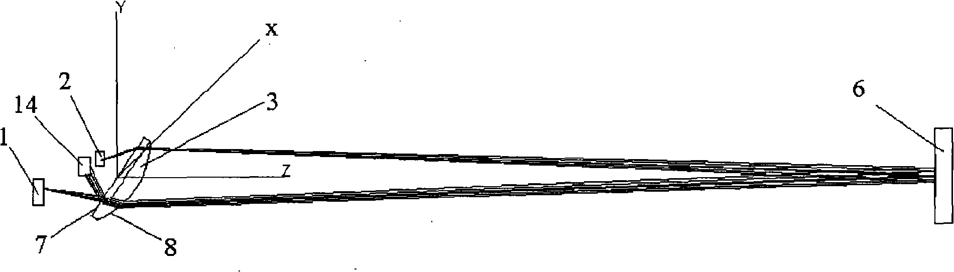
[0055] Such as Figure 4 , 5 As shown, this embodiment describes a gas measuring device and method, and the difference between this embodiment and Embodiment 1 is:

[0056] (1) The convex surface of the plano-convex lens 3 faces the laser 1 and the sensor 2, and the included angle between the main optical axis of the plano-convex lens 3 and the longitudinal axis of the measurement channel 12 is 13°.

[0057] (2) The angle between the central axis of the measuring light emitted by the laser 1 and the Z axis is 11.8°, so that the measuring light is obliquely incident on the optical curved surface 8 of the plano-convex lens 3 . The included angle between the central axis of the measuring light and the normal of the incident point on the optical curved surface 8 is 21°. In the present embodiment, the divergence angle of the measuring light is 13°, and the included angle between the measuring light and the normal of the optical interface at the incident point of the plano-convex ...

Embodiment 3

[0062] Such as Figure 6 , 7 As shown, this embodiment describes a gas measuring device and method, and the difference between this embodiment and Embodiment 1 is:

[0063] (1) The position of the laser 1 in the Y-axis direction is higher than that of the sensor 2, the convex surface of the plano-convex lens 3 faces the laser 1 and the sensor 2, and the included angle between the main optical axis of the plano-convex lens 3 and the longitudinal axis of the measurement channel 12 is 8 °.

[0064] (2) The angle between the central axis of the measuring light emitted by the laser 1 and the Z axis is 8.5°, so that the measuring light is obliquely incident on the optical curved surface 8 of the plano-convex lens 3 . The included angle between the central axis of the light beam and the normal line of the incident point of the optical curved surface 8 is 34°, and the divergence angle of the measured light is 13° in this embodiment. The method of measuring the light and its optical ...


PUM


Abstract

The invention relates to a gas measurement method and a gas measurement device, which are mainly used for detecting gas parameters. The device comprises an analysis unit and a laser, a sensor, a convergent component and an optical reflector which are arranged inside a supporting device, wherein, the sensor is connected with the analysis unit. The measurement method is as follows: the laser gives out laser to the convergent component which is obliquely arranged; the laser is converged by the convergent component, passes through gas to be measured and then is emitted to the optical reflector; after the laser is reflected by the reflector, the laser passes through the gas to be measured and the convergent component again and is then received by the sensor; and the sensor transmits received signals to the analysis unit, and the parameters of the gas to be measured are obtained through analysis of the analysis unit. The gas measurement method and the gas measurement device have the advantages of advanced method, reasonable and skillful light path design, low optical noise, small number of parts, high measuring precision, convenient assembly and stable and reliable operation.

Description

technical field [0001] The invention relates to a gas measurement method and its device, which are mainly used for detecting gas parameters. Background technique [0002] Semiconductor laser absorption spectroscopic analysis technology can be used to analyze gas and measure the content of chemical components in liquid, as well as analyze physical parameters such as gas temperature and velocity, and its application is becoming more and more extensive. This technique is a highly sensitive gas analysis technique. The principle of this technology is that when a semiconductor laser beam of a specific frequency passes through the measured gas, the light intensity is attenuated by the measured gas’s absorption of the beam energy, which can be accurately expressed by the Beer-Lambert relationship: [0003] I(v)=I 0 (v)exp[-S(T)φ(v)PXL] [0004] where I 0 (v) and I(v) respectively represent the light intensity when the laser with frequency v is incident and after passing through ...

Claims


Application Information

Patent Timeline
IPC IPC(8): G01N21/39
Inventor 顾海涛黄伟王健
Owner FOCUSED PHOTONICS
Why Eureka
Try Eureka