
Image encoding method, device using the same

An image encoding and image technology, applied in the field of image encoding, can solve the problems of subjective inconsistency, the circuit scale of the encoding device becomes larger, and the end of image frame encoding cannot be guaranteed, and the effect of shortening the encoding delay is achieved.

Inactive Publication Date: 2011-09-14
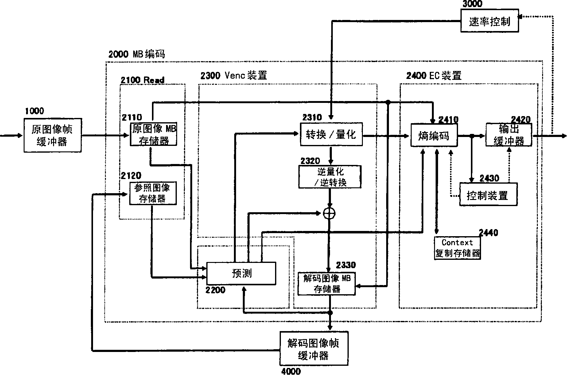
NEC CORP
View PDF1 Cites 0 Cited by
  • Summary
  • Abstract
  • Description
  • Claims
  • Application Information

AI Technical Summary

Problems solved by technology

Therefore, in the case of simply pipelining the existing encoding device, it is impossible to ensure that the encoding of the image frame is completed in real time.
[0072] Needless to say, the above-mentioned encoding delay can be avoided if a plurality of MB encoding devices 2000 are provided, but there is another problem that the circuit scale of the encoding device increases.
[0073] In addition, in the above-mentioned original image PCM re-encoding, since the frequency characteristic of the MB reconstructed from the original image by the original-image PCM re-encoding is different from that of the surrounding MB reconstructed from the decoded image, there is also a subjective inconsistency in image quality. question on
This problem is unavoidable with only a plurality of MB encoding devices 2000

Method used


Image

  • Image encoding method, device using the same
  • Image encoding method, device using the same
  • Image encoding method, device using the same

Examples


no. 2 Embodiment approach

[0149] Figure 11 shows that the number of bits after entropy encoding for the processing target MB is estimated before entropy coding, and when the estimated number of bits seems to exceed a predetermined value, by applying the decoded image PCM coding described later to the processing target MB, A configuration of an image coding device according to a second embodiment of the invention for further shortening coding delay.

[0150] and Figure 8 Compared with the image coding device according to the first embodiment of the present invention, the image coding device according to the second embodiment of the present invention includes the MB bit estimation device 2450 . In addition, since the EC device 2400 (entropy encoding device 2410) of the invention uses the estimated number of bits supplied from the MB bit estimation device 2450 as input, its operation is different from that of the EC device 2400 according to the first embodiment of the invention.

[0151] The MB bit esti...

no. 3 Embodiment approach

[0178] In the above-mentioned image coding apparatus according to the second embodiment, if the parameter α of Equation (9) is set small and the estimated bit number MB_est_bit is estimated to have a sufficient margin with respect to the predetermined value MB_bit_th, the output bit of entropy coding The number must not exceed the specified MB_bit_th. That is to say, no further coding is required.

[0179] In this case, no further encoding is required, no Figure 11 The context replication memory 2440 does not need to monitor the number of output bits of the entropy encoding. As a result, the image encoding device can be configured more simply. ( Figure 14 ).

[0180] refer to Figure 15 , to describe the operation of the EC device 2400 in the case of this structure.

[0181] In step S20000, it is determined whether the estimated bit number MB_est_bit is equal to or less than a predetermined value MB_bit_th. If it is the following, it is step S10000. If not the follow...


PUM


Abstract

When entropy-encoding a converted quantized amount obtained by converting an image into a frequency region and quantizing it, if the output code bit quantity of the entropy encoding exceeds a predetermined amount, an image obtained by rebuilding the converted quantized value is outputted from an image encoding device. This guarantees an encoding delay caused by re-encoding to be a constant time without increasing the circuit size of the encoding device and provides an image encoding device of a subjectively high quality.

Description

technical field [0001] The present invention relates to an image coding technique based on variable length coding or arithmetic coding isentropic coding. In particular, it is preferably used in an image coding device. Background technique [0002] Conventionally, an image encoding device digitizes a moving image input from the outside, and then performs encoding processing according to a predetermined image encoding method to generate a bit stream (bit stream) which is encoded data. [0003] As the above-mentioned image coding method, there is ISO / IEC 14496-10 Advance Video Coding (non-patent document 1 ISO / IEC 14496-10 Advance Video Coding), which has been standardized in recent years. Existing image encoding device). [0004] refer to figure 1 , explaining the structure and operation of a conventional image encoding device that takes digitized image frames as input and outputs a bit stream. [0005] refer to figure 1 , the existing image encoding device is composed of...

Claims


Application Information

Patent Timeline
Patent Type & Authority Patents(China)
IPC IPC(8): H04N7/30H04N19/50H03M7/36H03M7/40H04N19/126H04N19/13H04N19/132H04N19/146H04N19/149H04N19/196H04N19/426H04N19/436H04N19/503H04N19/593H04N19/60H04N19/61H04N19/91
CPCH04N19/00781H04N19/00121H04N19/00187H04N19/00193H04N19/00309H04N19/00127H04N19/00296H04N19/00278H04N19/0009H04N19/176H04N19/13H04N19/15H04N19/124H04N19/132H04N19/60
Inventor 蝶野庆一仙田裕三宫本义弘
Owner NEC CORP
Learn More