Highly effective natural energy heat pump

A natural energy and high-efficiency technology, applied in the field of heat pump systems and high-efficiency natural energy heat pumps, can solve the problems of low refrigerant evaporation and heat absorption capacity, high return air and exhaust pressure, and slow heating speed, etc., to achieve long service life, Stable working performance, efficient and rapid heating effect

Inactive Publication Date: 2008-10-22
惠州市思想科技有限公司
View PDF0 Cites 0 Cited by
  • Summary
  • Abstract
  • Description
  • Claims
  • Application Information

AI Technical Summary

Problems solved by technology

When the ambient temperature of the condenser is low, it is easy to cause insufficient refrigerant quantity of the system evaporator, too low return air pressure, too little return air and oil return of the compressor, and excessive exhaust temperature due to excessive stagnant liquid in the condenser. In addition, although the relative heating energy efficiency is relatively high at this time, due to the small amount of refrigerant sucked into the compressor, the compressor is in a light-load working state, the heating power of the heat pump is not easy to exert, and the heating speed is not ideal; when the condenser When the ambient temperature is high, it is easy to cause adverse phenomena such as excessive refrigerant quantity of the system evaporator, excessive return gas and exhaust pressure due to insufficient condensation and liquefaction of the high-temperature gaseous refrigerant, and, although the compressor is working under heavy load at this time The relative input power is relatively high, but due to the high condensing temperature and low heat absorption capacity of refrigerant evaporation, the heating power of the heat pump is also low, and the heating speed is also slow. Furthermore, the heating energy efficiency of the heat pump is relatively Low, the system is unstable
Under the existing conventional technology, the actual use effect and actual service life of the heat pump are not fully satisfactory, which also greatly limits the popularization and application of this new generation of energy-saving and environmentally friendly products. Methods to alleviate the above shortcomings of heat pumps, but the results are not ideal

Method used


Image

  • Highly effective natural energy heat pump
  • Highly effective natural energy heat pump
  • Highly effective natural energy heat pump

Examples


Embodiment 1

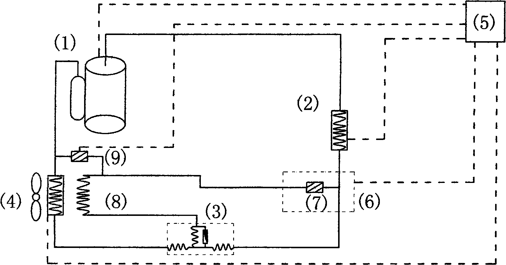
[0016] Embodiment 1: A high-efficiency natural energy heat pump mainly consists of a compressor (1), an indoor heat exchanger (2), a throttling device (3), and an outdoor heat exchanger (4), and is composed of an appropriate amount of copper pipes, etc. The accessories are connected in sequence to form a refrigerant closed cycle passage system, and the system is controlled by the electric control device (5). The diverter device (6) is divided into two paths, one of which is connected to the throttling device (3) through corresponding copper pipes and other fittings, and the other path is connected with a natural The inlet of the natural energy heat exchanger (8) is connected, the outlet of the natural energy heat exchanger (8) is connected with the throttling device (3) through corresponding copper pipes and other fittings, and the inlet of a return air valve (9) is also connected with the The refrigerant inlet of the natural energy heat exchanger (8) is connected, and the out...

Embodiment 2

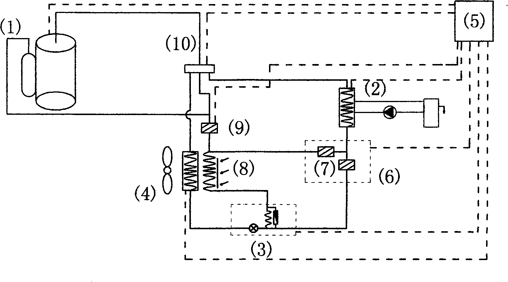
[0019] Embodiment 2: A high-efficiency natural energy heat pump mainly includes a compressor (1), a four-way reversing valve (10), an indoor heat exchanger (2), a throttling device (3), and an outdoor heat exchanger (4) It is composed of a proper amount of copper pipes and other fittings to form a refrigerant closed cycle passage system. This system is controlled by an electric control device (5). In particular, in the above system, the refrigerant outlet of the indoor heat exchanger (2) passes through A diversion device (6) equipped with a control valve (7) is divided into two circuits, one of which is connected in series with a control valve (7) and connected with the throttling device (3) through corresponding copper pipes and other fittings. The other path of another control valve (7) is connected to the inlet of a natural energy heat exchanger (8) through corresponding fittings such as copper pipes, and the outlet of the natural energy heat exchanger (8) is connected to th...

Embodiment 3

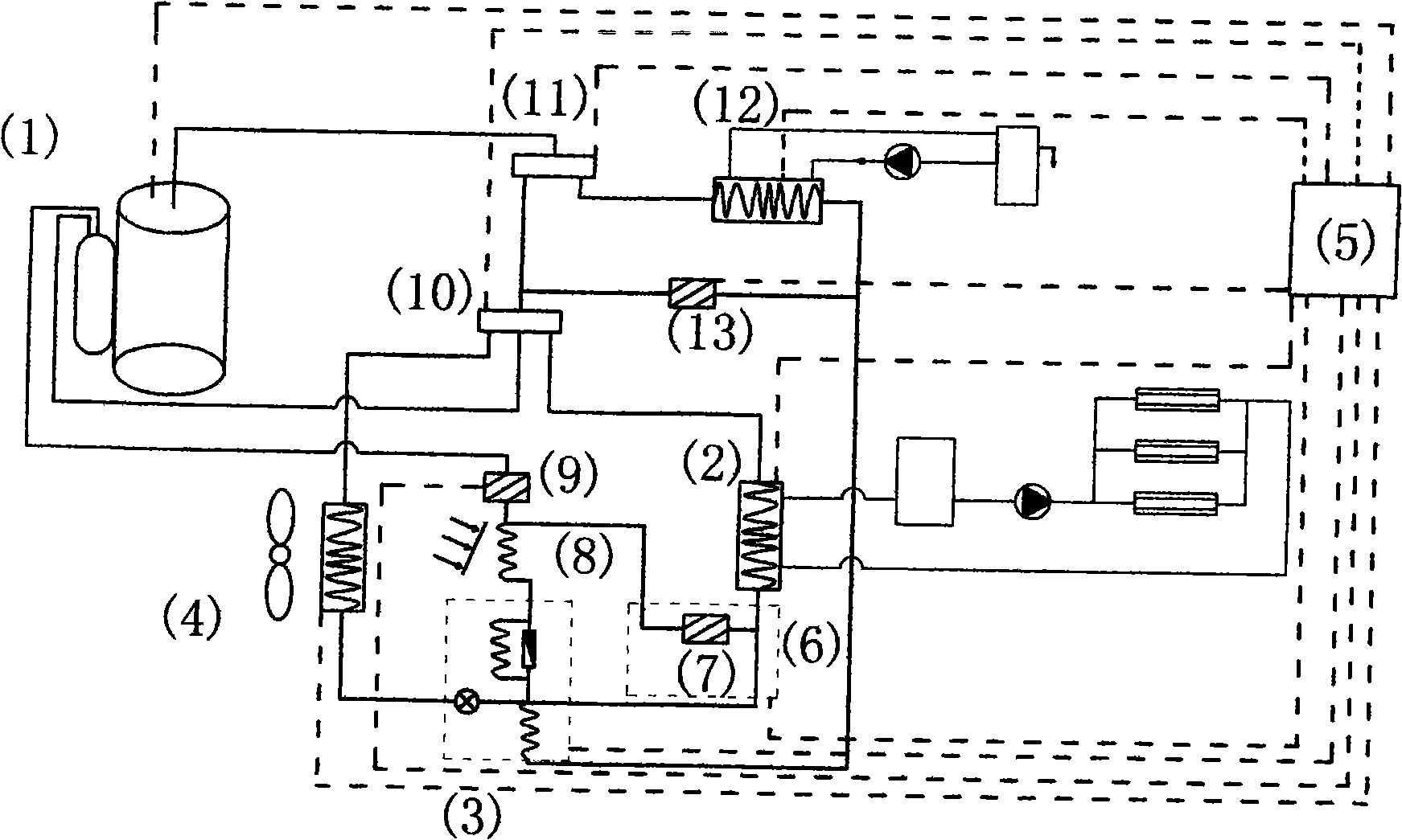
[0022] Embodiment 3: A high-efficiency natural energy heat pump mainly includes a compressor (1), a gating valve (11), a water condenser (12), a gating device (13), a four-way reversing valve (10), an indoor The heat exchanger (2), the throttling device (3), and the outdoor heat exchanger (4) are connected in turn by a proper amount of copper pipes and other accessories to form a refrigerant closed circulation path system. The system consists of an electric control device (5 ) control work, in particular, the refrigerant outlet of the indoor heat exchanger (2) in the above system is divided into two paths through a diverter device (6) with a control valve (7), one of which passes through corresponding copper pipes and other fittings and joints. flow device (3), connected in series with a control valve (7), the other channel is connected to the inlet of a natural energy heat exchanger (8) through corresponding copper pipes and other fittings, and the outlet of the natural energy...


PUM


Abstract

The present invention discloses a highly-effective natural energy heat pump, belonging to the heat pump application technical field. A refrigerant closed circulation system is formed by connected refrigerant channels such as a compressor (1), an indoor heat exchanger (2), a throttling device (3) and an outdoor heat exchanger (4), etc., and is controlled by an electric control device (5). The heat pump is characterized in that: a flow splitting device (6) is connected with a control valve (7) in series; the indoor heat exchanger (2) is divided into at least two refrigerant output channels through the flow splitting device (6), wherein at least one channel is connected with the throttling device (3); and at least the other channel in which the flow can be controlled by the control valve (7), is connected with an inlet of at least one natural energy heat exchanger (8). The outlet of the natural energy heat exchanger (8) is connected with the throttling device (3), and the inlet of the natural energy heat exchanger (8) is further connected with an inlet of an air returning valve (9). The outlet of the air returning valve (9) is connected with an air returning pipeline. The heat pump is capable of using natural energy to effectively and quickly heat, reducing frost, preventing the compressor (1) from oil deficiency, liquid impact and high-temperature high pressure damages. The heat pump is long in service life and wide in application range.

Description

Technical field [0001] The invention relates to a heat pump system, in particular to a high-efficiency natural energy heat pump, which belongs to the technical field of heat pump applications. Background technique [0002] Heat pumps have obvious energy-saving advantages because their heating energy efficiency ratio is always greater than 1, and they have been vigorously promoted and applied in modern society where energy is scarce. After the refrigerant enters the condenser, it releases heating heat and condenses into a medium-temperature and medium-pressure liquid refrigerant, which is then decompressed into a low-temperature and low-pressure refrigerant through the throttling device, then flows into the evaporator to absorb heat energy, and finally returns to the compressor to complete the cycle . When the ambient temperature of the condenser is low, it is easy to cause insufficient refrigerant quantity of the system evaporator, too low return air pressure, too little re...

Claims


Application Information

Patent Timeline
Patent Type & Authority Applications(China)
IPC IPC(8): F25B13/00
Inventor 秦恩溢
Owner 惠州市思想科技有限公司
Why Eureka
Try Eureka